Hyundai Santa Fe (2006 year). Manual - part 654


  Index      Hyundai     Hyundai Santa Fe - service repair manual 2006 year


Search            


Content   ..  652  653  654  655   ..


Hyundai Santa Fe (2006 year). Manual - part 654


GENERAL

GI -17

GENERAL SERVICE INFORMATION

PROTECTION OF THE VEHICLE
Always be sure to cover fenders, seats, and floor areas
before starting work.
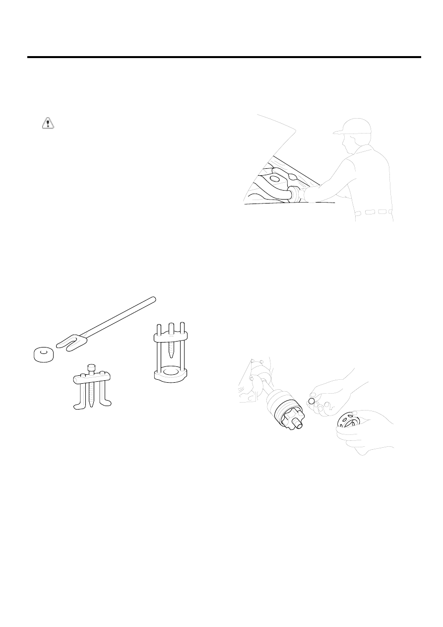
CAUTION

The support rod must be inserted into the hole
near the edge of the hood whenever you inspect
the engine compartment to prevent the hood from
falling and causing possible injury.
Make sure that the support rod has been released
prior to closing the hood. Always check to be sure
the hood is firmly latched before driving the vehi-
cle.

PREPARATION OF TOOLS AND MESURING
EQUIPMENT

Be sure that all necessary tools and measuring equipment
are available starting work.

SPECIAL TOOLS

Use special tools when they are required.

EAKE005A

REMOVAL OF PARTS

First find the cause of the problem and then determine
whether removal or disassembly before starting the job.

EAKE005B

DISASSEMBLY

If the disassembly procedure is complex, requiring many
parts to be disassembled, all parts should be disassem-
bled in a way that will not aggect their performance or ex-
ternal appearance.
1.

Inspection of parts
Each part, when removed, should be carefulley on
spected for malfunction, deformation, damage, and
other problems.

EAKE005C

GI -18

GENERAL INFORMATION

2.

Arrangement of parts
All disassembled parts should be carefully arranged
for effective reassembly.
Be sure to separate and correctly identify the parts to
be repllaced from those that will be used again.

EAKE005D

3.

Cleaning parts for reuse
All parts to be used again should be carefully and
thoroughly cleaned by an appropriate method.

EAKE005E

PARTS

When replacing parts, use HYUNDAI genuine parts.

EAKE005F

REPLACEMENT

Standard values, such as torques and certain adjust-
ments, must be strictly observed in the reassembly of all
parts.
If removed, the following parts should always be replaced
with new ones.
1.

Oil seals

2.

Gaskets

3.

O-rings

4.

Lock washers

5.

Cotter pins (split pins)

6.

Plastic nuts

EAKE005G

Depending on their location.

GENERAL

GI -19

7.

Selalant should be applied to gaskets.

8.

Oil should be applied to the moving components of
parts.

9.

Specified oil or grease should be applied to the pre-
scribed locations (oil seals, etc) before assembly.

EAKE005H

ADJUSTMENT

Use gauges and testers to adjust correclty the parts to
standard values correctly.

ELECTRICAL SYSTEM

1.

Be sure to disconnect the battery cable from the neg-
ative (-) terminal of the battery.

2.

Never pull on the wires when disconnecting connec-
tors.

3.

Locking connectors will click when the connector is
secure.

4.

Handle sensors and relays carefully. Be careful not to
drop them against other parts.

EAKE005I

RUBER PARTS AND TUBES

Always prevent gasoline or from touching rubber parts or
tubing.

EAKE005J

MEASURING BODY DIMENSIONGS

1.

Basically, all measurements in this manual are taken
with a tracking gauge.

2.

When a measuring tape is used, check to be sure
there is no elongation, twisting or bending.

3.

For measuring dimensions, both projected dimen-
sioners and actual - measurement dimensions are
used in this manual.

DIMENSIONS PROJECTED

1.

These are the dimensions measured when the mea-
surement points are projected from the vehicle’s sur-
face, and are the reference dimensions used for used
for body alterations.

2.

If the length of the tracking gauge probes is ad-
justable, measure it by lengthening one of two probes
as long as the different value in height of the two
surface.

Height

Projected dimension

EAKE005K

GI -20

GENERAL INFORMATION

MEASURING ACTUAL DIMENSIONS

1.

These dimensions indicate the actual linear distance
between mesaurement points, and are used as the
reference dimensions when a tracking gauge is used
for measurement.

2.

First adjust both probes to the same length (A=A’)
before measurement.

NOTE

Check the probes and gauge itself to make sure there
is no free play.

Actually-measured dimension

EAKE005L

MEASUREMENT POINT

Measurements should be taken at the center fo the hole.

Hole center

EAKE005M

CHECKING CABLES AND WIRES

1.

Check the terminal for tightness.

2.

Check terminals and wires for corrosion from battery
electrolyte, etc.

3.

Check terminals and wires for open corcuits.

4.

Check wire insulation and coating for damage, cracks
and degrading.

5.

Check the conductive parts of terminals for contact
with other metallic parts (vehicle body and other
parts).

6.

Check grounded parts to verify that there is complete
continuity between thier attaching bolt(s) and the ve-
hicle’s body.

7.

Check for incorrect wiring.

8.

Check that the wiring is so clamped to the prevent
contact with sharp corners of the vehicle body, etc.
or hot parts (exhaust manifold, etc.)

9.

Check that the wiring is clamped firmy to provide
enough clearance from the fan pulley, fan belt and
other rotating or moving parts.

10. Check that the wiring has a little space so that it can

vibrate between fixed and moving parts such as the
vehicle body and the engine.

EAKE005N


Content   ..  652  653  654  655   ..