Hyundai Santa Fe (2006 year). Manual - part 629
FLA -582
FUEL SYSTEM
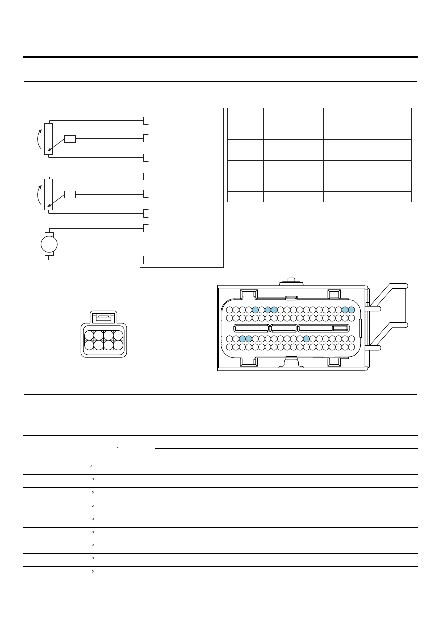
SCHEMATIC DIAGRAM
E6FFC24B
[CIRCUIT DIAGRAM]
[HARNESS CONNECTORS]
[CONNECTION INFORMATION]
ETC MODULE
C86
Terminal
Connected to
Function
1
2
ETC Module (C86)
3
4
PCM C30-B (16)
TPS 1 Reference Voltage (+5V)
5
6
PCM C30-B (57)
TPS 2 Signal
7
PCM C30-B (48)
TPS 1 Signal
8
PCM C30-B (14)
TPS 1 Ground
PCM (C30-B)
PCM
C30-B
1
2
5
6
3
4
7
8
PCM C30-B (2)
ETC Motor [+] Control
PCM C30-B (58)
TPS 2 Ground
TPS 2 Reference Voltage (+5V)
PCM C30-B (13)
ETC Motor [-] Control
PCM C30-B (1)
1
21
2
22
3
23
4
24
5
25
6
26
7
27
8
28
9
29
10
30
11
31
12
32
13
33
14
34
15
35
16
36
17
37
18
38
19
39
20
40
41
61
42
62
43
63
44
64
45
65
46
66
47
67
48
68
49
69
50
70
51
71
52
72
53
73
54
74
55
75
56
76
57
77
58
78
59
79
60
80
1
2
4
TPS 1
TPS 2
ETC MOTOR
16 - Reference Voltage (+5V)
48 - TPS 1 Signal
14 - GND
6
3
7
13 - Reference Voltage (+5V)
57 - TPS 2 Signal
58 - GND
8
5
2 - ETC Motor [+]
1 - ETC Motor [-]
M
SCMF16101L
SPECIFICATION
E6C4A697
Output voltage(V) [Vref=5.0V]
Throttle opening (
)
TPS1
TPS2
0
0.0V
5.0V
10
0.5V
4.5V
20
0.9V
4.1V
30
1.4V
3.6V
40
1.8V
3.2V
50
2.3V
2.7V
60
2.7V
2.3V
70
3.2V
1.8V
80
3.6V
1.4V