Hyundai Santa Fe (2006 year). Manual - part 590


  Index      Hyundai     Hyundai Santa Fe - service repair manual 2006 year


Search            


Content   ..  588  589  590  591   ..


Hyundai Santa Fe (2006 year). Manual - part 590


FLA -426

FUEL SYSTEM

DTC P0506 IDLE AIR CONTROL SYSTEM-RPM LOWER THAN EXPECTED
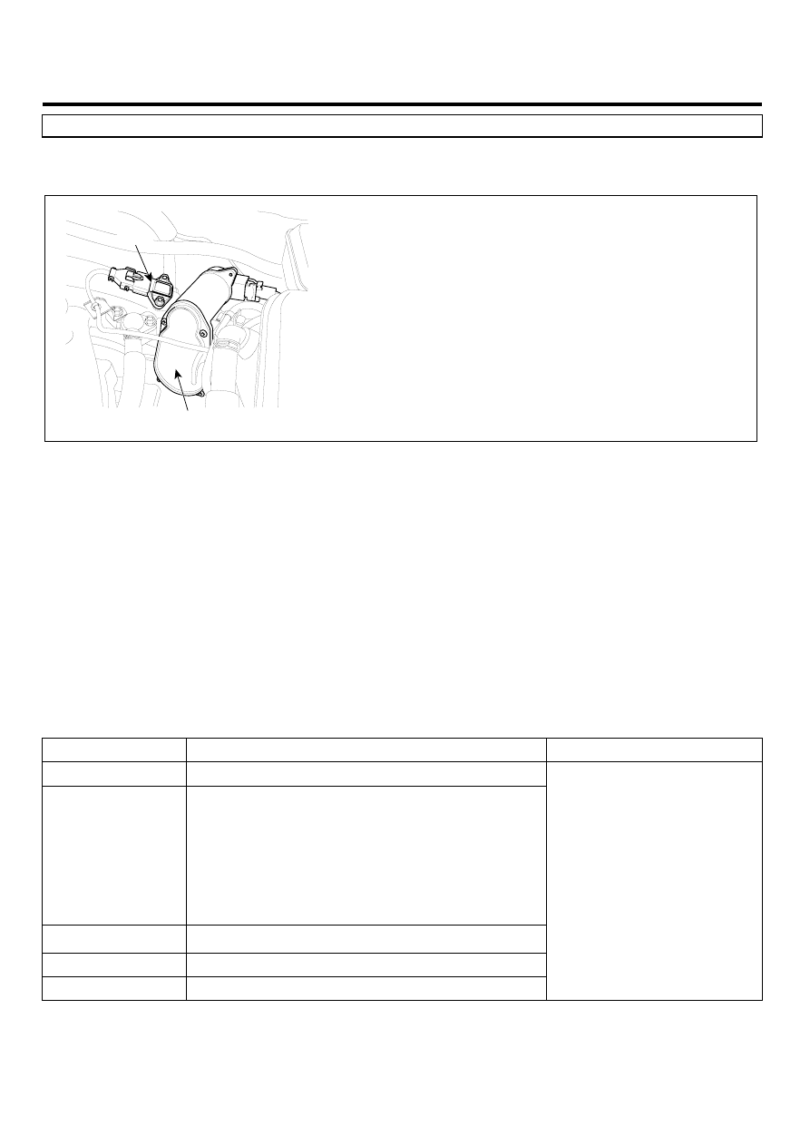
COMPONENT LOCATION

EA62E8A4

ETC Module (TPS + ETC Motor)

MAPS

SCMF16192L

GENERAL DESCRIPTION

E4D4857B

The idle speed is controlled by the Electrical Throttle Control(ETC) System. ETC system is composed of the throttle
motor to operate the throttle valve and the throttle position sensor to detect the opening angle of the throttle valve, the
accelerator pedal position sensor to detect the accelerator pedal position and the one valve type throttle body. The ECM
controls the throttle motor to provide the proper throttle valve opening angle for the target idle speed.

DTC DESCRIPTION

E0E16B88

Checking idle RPM under detecting condition, if if the idle speed is 100RPM below desired idle speed, PCM sets P0506.
MIL(Malfunction Indication Lamp) turns on when the malfunction lasts till cosecutive 2 driving cycle.

DTC DETECTING CONDITION

EBD800A3

Item

Detecting Condition

Possible cause

DTC Strategy

• Determines if a low idle condition exists.

Enable Conditions

• Normal Idle conditions
• Canister Purge Fuel Flow ≤ 100
• Barometric Pressure 〉 72kPa
• Engine running ≥ 2 sec
• Air Intake Temperature ≥ -20℃ (-4℉)
• Coolant Temperature ≥ 0℃ (32℉)
• 11V ≤ Ignition Voltage ≤ 16V
• Above conditions met period 〉3 sec

Thresh old value

• Real engine speed - Target engine speed〈 -100rpm

Diagnosis Time

• Continuous

MIL On Condition

• 2 driving cycles

• Poor connection
• Intake/Exhaust system

for blockage

• Throttle plate for carbon

deposits

• Faulty ETS motor
• Faulty TPS
• Faulty ETS system
• Faulty PCM

MONITOR DTC STATUS

E6751FA9

1.

Check DTC Status

DTC TROUBLESHOOTING PROCEDURES

FLA -427

1)

Connect scantool to Data Link Connector(DLC).

2)

IG "ON".

3)

Select "Diagnostic Trouble Codes(DTCs)" mode, and then Press F4(DTAL) to check DTC’s information from the
DTCs menu

4)

Read "DTC Status" parameter.

SCMF16159L

5)

Is parameter displayed "Present fault"?

YES

▶ Go to "Terminal and connector inspection" procedure.

NO

▶ Fault is intermittent caused by poor contact in the sensor’s and/or PCM’s connector or was repaired and PCM
memory was not cleared. Thoroughly check connectors for looseness, poor connection, ending, corrosion, con-
tamination, deterioration, or damage. Repair or replace as necessary and go to "Verification of Vehicle Repair"
procedure.

TERMINAL AND CONNECTOR INSPECTION

EAC4DDC3

1.

Many malfunctions in the electrical system are caused by poor harness and terminals. Faults can also be caused by
interference from other electrical systems, and mechanical or chemical damage.

2.

Thoroughly check connectors for looseness, poor connection, bending, corrosion, contamination, deterioration, or
damage.

3.

Has a problem been found?

YES

▶ Repair as necessary and go to "Verification of Vehicle Repair" procedure

NO

▶ Go to " System Inspection " procedure

FLA -428

FUEL SYSTEM

SYSTEM INSPECTION

ECD0849A

1.

Check intake/exhaust system for blockage

1)

Visually/physically inspect the following items:
- Air cleaner filter element for excessive dirt or for any foreign objects
- Hoses of intake system for blockage
- Throttle body inlet for damage or for any foreign objects
- Throttle plate for carbon deposits
- Restricted exhaust system

2)

Has a problem been found in any of the above areas?

YES

▶ Replace or repair as necessary and go to "Verification of Vehicle Repair" procedure

NO

▶ Go to "Visually check ETS System" as below

2.

Visually check ETS System

1)

Ignition "OFF"

2)

Remove the air hose between MAF sensor and Throttle body.

3)

Visually check the overall ETS system(Throttle valve,ETS motor,APS and TPS).

4)

Has a problem been found?

YES

▶ Repair or replace as necessary and go to "Verification of Vehicle Repair" procedure.

NO

▶ Go to " Component Inspection" procedure.

COMPONENT INSPECTION

EDF78774

1.

Check ETS motor

1)

Ignition "OFF"

2)

Disconnect ETS motor connector

3)

Measure resistance between terminals "1" and "2" of the ETS motor connector.

Specification: Approx. 1.275 ~ 1.725Ω at 20℃(68 F)

4)

Is the measured resistance within specifications?

YES

▶ Go to "Check TPS" as below

NO

DTC TROUBLESHOOTING PROCEDURES

FLA -429

▶ Substitute with a known-good ETS motor and check for proper operation. If the problem is corrected, replace
ETS motor and then do "ETS Initialization" and go to "Verification of Vehicle Repair" procedure.

2.

Check TPS

1)

Disconnect TPS connector and measure resistance between terminals 4 and 8 of the TPS connector.

Specification : Approx. 4.0~6.0kΩ ( with throttle valve fully closed) at 20 C(68 F)

2)

Disconnect TPS connector and measure resistance between terminals 1 and 5 of the TPS connector.

SPECIFICATION:

Item

Sensor Resistance at 20℃ (68 F)

TPS 1

4.0 ~ 6.0 ㏀

TPS 2

2.72 ~ 4.08 ㏀

3)

Are the TPS resistance within specifications?

YES

▶ Substitute with a known-good PCM and check for proper operation. If the problem is corrected,replace PCM
and then go to "Verification of Vehicle Repair" procedure. If PCM needs to be replaced, do "ETS Initialization"
after it is replaced.

NO

▶ Substitute with a known-good TPS and check for proper operation.If the problem is corrected, replace TPS
and then do "ETS Initialization". And go to "Verification of Vehicle Repair" procedure.

※ Procedure of ETS Initialization
1. Erase the trouble codes on PCM
2. Turn the ignition key off and keep this condition until the main relay is turned off.(It will takes 10 second)
3. Turn ignition key on more than 1second to record the throttle motor position on the EEPROM

VERIFICATION OF VEHICLE REPAIR

EDACDFAA

After a repair, it is essential to verify that the fault has been corrected.

1.

Monitor and record the Freeze Frame Data for the Diagnostic Trouble Code(DTC) which has been diagnosed.

2.

Using a Scantool, Clear the DTCs

3.

Operate the vehicle within conditions noted in the freeze frame data or enable conditions

4.

Monitor that all rediness test have been verified as " Complete "

5.

Are any DTCs present ?

YES

▶ Go to the applicable troubleshoooting procedure.

NO

▶ System is performing to specification at this time.


Content   ..  588  589  590  591   ..