Hyundai Santa Fe (2006 year). Manual - part 582


  Index      Hyundai     Hyundai Santa Fe - service repair manual 2006 year


Search            


Content   ..  580  581  582  583   ..


Hyundai Santa Fe (2006 year). Manual - part 582


FLA -394

FUEL SYSTEM

1)

Connect scantool to Data Link Connector(DLC).

2)

IG "ON".

3)

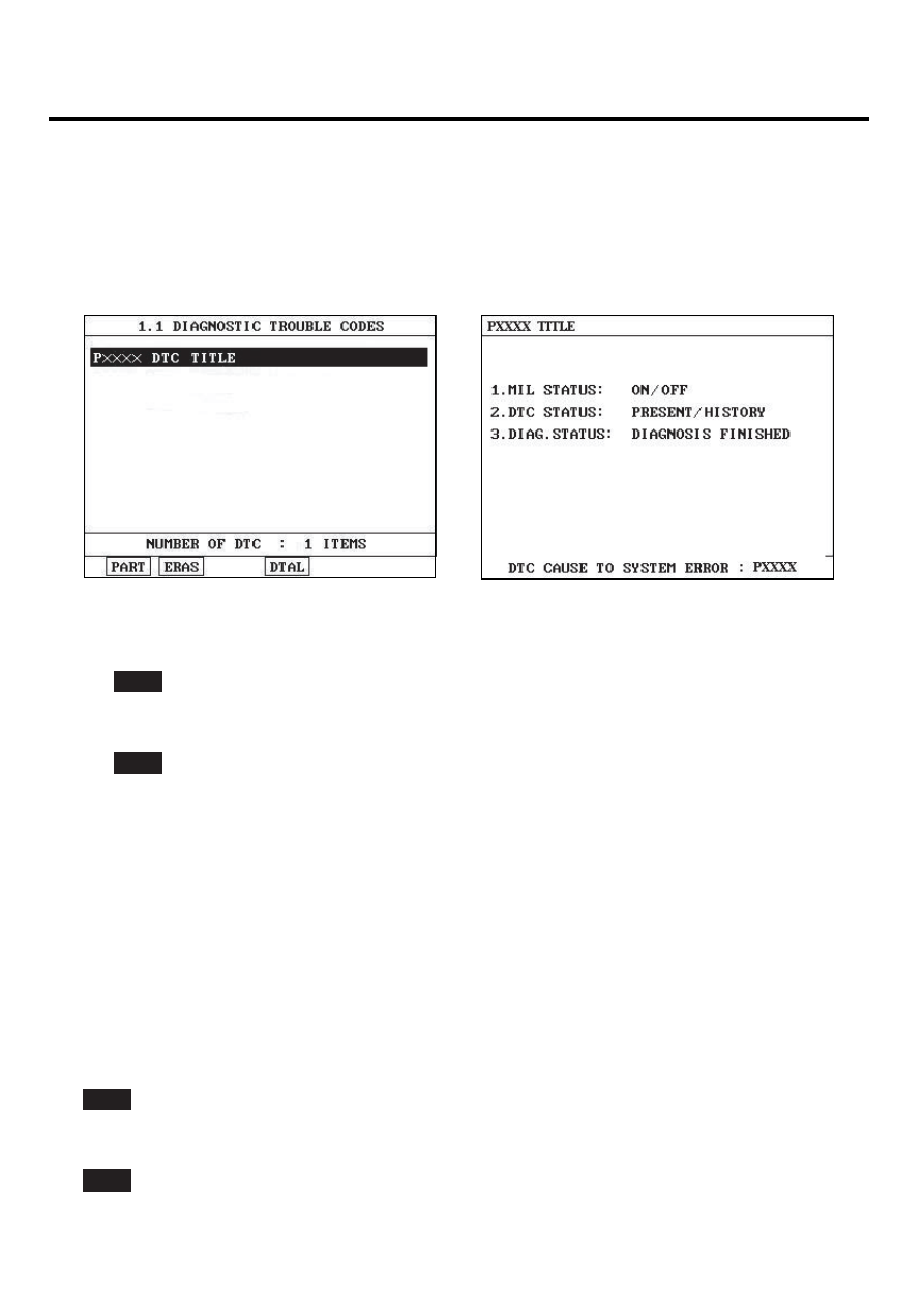
Select "Diagnostic Trouble Codes(DTCs)" mode, and then Press F4(DTAL) to check DTC’s information from the
DTCs menu

4)

Read "DTC Status" parameter.

SCMF16159L

5)

Is parameter displayed "Present fault"?

YES

▶ Go to "Terminal and connector inspection" procedure.

NO

▶ Fault is intermittent caused by poor contact in the sensor’s and/or PCM’s connector or was repaired and PCM
memory was not cleared. Thoroughly check connectors for looseness, poor connection, ending, corrosion, con-
tamination, deterioration, or damage. Repair or replace as necessary and go to "Verification of Vehicle Repair"
procedure.

TERMINAL AND CONNECTOR INSPECTION

EB4A8784

1.

Many malfunctions in the electrical system are caused by poor harness and terminals. Faults can also be caused by
interference from other electrical systems, and mechanical or chemical damage.

2.

Thoroughly check connectors for looseness, poor connection, bending, corrosion, contamination, deterioration, or
damage.

3.

Has a problem been found?

YES

▶ Repair as necessary and go to "Verification of Vehicle Repair" procedure

NO

▶ Go to " Power Circuit Inspection " procedure.

DTC TROUBLESHOOTING PROCEDURES

FLA -395

POWER CIRCUIT INSEPCTION

E79BA4AA

1.

Check voltage

1)

IG "OFF" and disconnect Ignition Coil connector.

2)

IG "ON" and ENG "OFF"

3)

Measure voltage between terminal 3 of ignition coil harness connector and chassis ground.

Specification : Approx. B+

4)

Is the measured voltage within specification ?

YES

▶ Go to "Control Circuit Inspection" procedure.

NO

▶ Check fuse connected to ignition coil for open.
▶ Repair open in harness, and go to "Verification of Vehicle Repair" procedure.

CONTROL CIRCUIT INSPECTION

EF5F3B09

1.

Check short to battery in harness.

1)

IG "OFF" and disconnect ignitioncoil connector and PCM connector.

2)

Measure resistance between terminals 1 and 3 of ignition coil harness connector.

Specification : Infinite

3)

Is the measured resistance within specification?

YES

▶ Go to "Check short to ground in harness" as follows.

NO

▶ Repair short to battery in harness, and go to "Verification of Vehicle Repair" procedure.

2.

Check short to ground in harness

1)

IG "OFF" and disconnect ignition coil connector and PCM connector.

2)

Measure resistance between terminal 1 of ignition coil harness connector and chassis ground.

Specification : Infinite

3)

Is the measured resistance within specification?

YES

▶ Go to "Check open in harness" as follows.

FLA -396

FUEL SYSTEM

NO

▶ Repair short to ground in harness, and go to "Verification of Vehicle Repair" procedure.

3.

Check open in harness

1)

IG "OFF" and disconnect Ignition Coil connector and PCM connector.

2)

[P0351] Measure resistance between terminal 1 of Ignition Coil harness connector and terminal C30-B (79) of
PCM harness connector.
[P0352] Measure resistance between terminal 1 of Ignition Coil harness connector and terminal C30-B (60) of
PCM harness connector.
[P0353] Measure resistance between terminal 1 of Ignition Coil harness connector and terminal C30-B (77) of
PCM harness connector.
[P0354] Measure resistance between terminal 1 of Ignition Coil harness connector and terminal C30-B (40) of
PCM harness connector.
[P0355] Measure resistance between terminal 1 of Ignition Coil harness connector and terminal C30-B (78) of
PCM harness connector.
[P0356] Measure resistance between terminal 1 of Ignition Coil harness connector and terminal C30-B (19) of
PCM harness connector.

Specification : Below 1Ω

3)

Is the measured resistance within specification?

YES

▶ Go to "Component Inspection" procedure.

NO

▶ Repair open in harness, and go to "Verification of Vehicle Repair" procedure.

COMPONENT INSPECTION

E401C34A

1.

Check Ignition Coil

1)

IG "OFF" and disconnect ignition coil connector.

2)

Measure resistance between terminals 3 and 1 of ignition coil connector.(Component side)

3)

Measure resistance between terminal 2 of ignition coil connector and out terminal of secondary ignition coil.

SPECIFICATION :

Primary Coil

Secondary Coil

Resistance

0.62Ω ± 10% [20℃(68℉)]

7.0kΩ ± 15% [20℃(68℉)]

DTC TROUBLESHOOTING PROCEDURES

FLA -397

3

2

1

2. Ground

SCMF16997L

4)

Is the measured resistance within specification?

YES

▶ Substitute with a known - good PCM and check for proper operation
▶ If the problem is corrected, replace PCM and go to "Verification of Vehicle Repair" procedure.

NO

▶ Substitute with a known - good Ignition Coil and check for proper operation.
▶ If the problem is corrected, replace Ignition Coil and go to "Verification of Vehicle Repair" procedure.

NOTE

There is a memory reset function on scantool that can erase optional parts automatically detected and memorized
by PCM. After testing PCM on the vehicle, use this function to reuse the PCM on the others

VERIFICATION OF VEHICLE REPAIR

ECD7629D

After a repair, it is essential to verify that the fault has been corrected.

1.

Monitor and record the Freeze Frame Data for the Diagnostic Trouble Code(DTC) which has been diagnosed.

2.

Using a Scantool, Clear the DTCs

3.

Operate the vehicle within conditions noted in the freeze frame data or enable conditions

4.

Monitor that all rediness test have been verified as " Complete "

5.

Are any DTCs present ?

YES

▶ Go to the applicable troubleshoooting procedure.

NO

▶ System is performing to specification at this time.


Content   ..  580  581  582  583   ..