Hyundai Santa Fe (2006 year). Manual - part 566


  Index      Hyundai     Hyundai Santa Fe - service repair manual 2006 year


Search            


Content   ..  564  565  566  567   ..


Hyundai Santa Fe (2006 year). Manual - part 566


FLA -330

FUEL SYSTEM

▶ Go to " Component Inspection" procedure.

NO

▶ Repair open in harness, and go to "Verification of Repair" procedure.

COMPONENT INSPECTION

EADB26DA

1.

Check TPS

1)

IG "OFF" and disconnect TPS connector.

2)

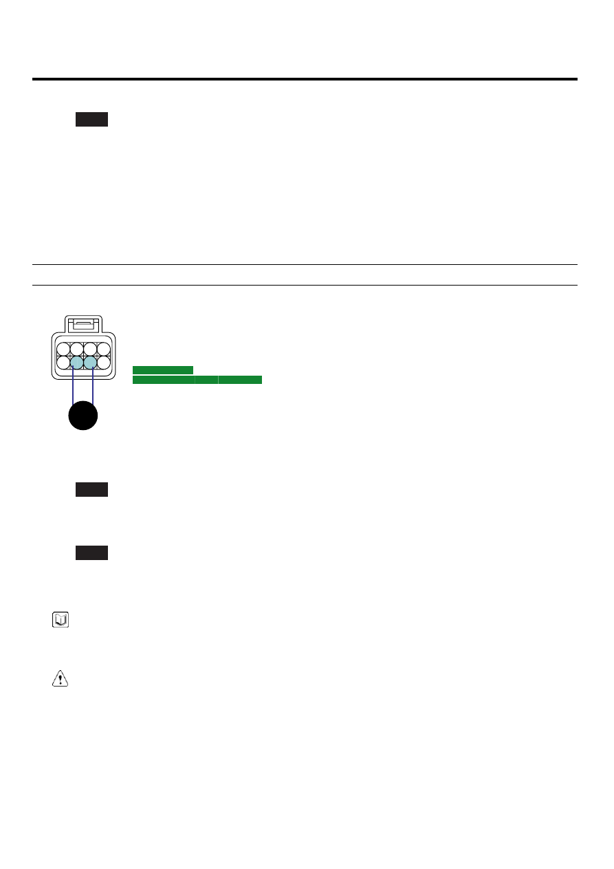
Measure resistance between terminals 7 and 6 of TPS connector.(Component side)

Specification : 2.7 ~ 4.1kΩ

1. TPS1 ground
2. TPS1 signal
3. TPS2 signal
4. TPS 1 Reference Voltage (+5V)
5. ETC motor[+] Control

8. ETC motor[-] Control

4

3

2

1

8

7

6

5

C86

SCMF16250L

3)

Is the measured resistance within specification?

YES

▶ Substitute with a known - good PCM and check for proper operation. If the problem is corrected, replace PCM
and go to "Verification of Vehicle Repair" procedure.

NO

▶ Substitute with a known - good TPS and check for proper operation. If the problem is corrected, replace TPS
and go to "Verification of Vehicle Repair" procedure.

NOTE

There is a memory reset function on scantool that can erase optional parts automatically detected and memorized
by PCM. After testing PCM on the vehicle, use this function to reuse the PCM on the others

CAUTION

Procedure of ETS Initialization
1.

Erase the trouble codes on PCM

2.

Turn the ignition key off and keep this condition until the main relay is turned off.(It will takes 10sec.)

3.

Turn ignition key on more than 1second to record the throttle motor position on the EEPROM

VERIFICATION OF VEHICLE REPAIR

ECE0E273

After a repair, it is essential to verify that the fault has been corrected.

1.

Monitor and record the Freeze Frame Data for the Diagnostic Trouble Code(DTC) which has been diagnosed.

DTC TROUBLESHOOTING PROCEDURES

FLA -331

2.

Using a Scantool, Clear the DTCs

3.

Operate the vehicle within conditions noted in the freeze frame data or enable conditions

4.

Monitor that all rediness test have been verified as " Complete "

5.

Are any DTCs present ?

YES

▶ Go to the applicable troubleshoooting procedure.

NO

▶ System is performing to specification at this time.

FLA -332

FUEL SYSTEM

DTC P0223 THROTTLE/PEDAL POSITION SENSOR/SWITCH "B" CIRCUIT
HIGH INPUT

COMPONENT LOCATION

E2DDF6EC

Refer to DTC P0222.

GENERAL DESCRIPTION

E1F46B90

Refer to DTC P0222.

DTC DESCRIPTION

E99F7095

Checking output signals from TPS2 every 8.5 sec. under detecting condition, if an output signal is above 4.75V for more
than 0.1 sec., PCM sets P0223. MIL(Malfunction Indication Lamp) turns on when the malfunction lasts till consecutive 2
driving cycle.

DTC DETECTING CONDITION

E0998B07

Item

Detecting Condition

Possible Cause

DTC Strategy

• Signal High

Enable condition

• IG "ON"

threshold value

• The signal voltage of TPS 〉4.75V

diagnosis time

• Continuous

(more than 0.1 sec. failure for every 8.5 sec.test)

MIL ON condition

• 2 driving cycles

• Poor connection
• Short to battery in signal

harness

• Open in ground harness
• TPS
• PCM

SPECIFICATION

EF1158C6

Refer to DTC P0222.

SCHEMATIC DIAGRAM

EB52B2D8

Refer to DTC P0222.

SIGNAL WAVEFORM AND DATA

EDE87B15

Refer to DTC P0222.

MONITOR DTC STATUS

EFDFE57A

Refer to DTC P0222.

TERMINAL AND CONNECTOR INSPECTION

ED7A94AD

Refer to DTC P0222.

DTC TROUBLESHOOTING PROCEDURES

FLA -333

SIGNAL CIRCUIT INSPECTION

E2452337

1.

Check voltage

1)

IG "OFF" and disconnect TPS connector.

2)

IG "ON and ENG "OFF"

3)

Measure voltage between terminal 3 of TPS harness connector and chassis ground.

Specification : Approx. 0V

4)

Is the measured voltage within specification?

YES

▶ Go to "Ground Circuit Inspection" procedure.

NO

▶ Go to "Check short to battery in harness" as follows.

2.

Check short to battery in harness

1)

IG "OFF" and disconnect TPS connector and PCM connector.

2)

Measure resistance between terminals 7 and 3 of TPS harness connector.

3)

Measure resistance between terminals 4 and 3 of TPS harness connector.

4)

Measure resistance between terminals 5 and 3 of TPS harness connector.

5)

Measure resistance between terminals 8 and 3 of TPS harness connector.

Specification : Infinite

6)

Is the measured resistance within specification?

YES

▶ Go to " Ground Circuit Inspection" procedure.

NO

▶ Repair short to battery in harness, and go to "Verification of Vehicle Repair" procedure.

GROUND CIRCUIT INSPECTION

E060618D

1.

IG "OFF" and disconnect TPS connector.

2.

IG "ON" and ENG "OFF"

3.

Measure voltage between terminal 8 of TPS harness connector and chassis ground.

4.

Measure voltage between terminals 8 and 6 of TPS harness connector.

Specification : Measurement "A" - Measurement ’B’ = Approx. below 200mV


Content   ..  564  565  566  567   ..