Hyundai Santa Fe (2006 year). Manual - part 565


  Index      Hyundai     Hyundai Santa Fe - service repair manual 2006 year


Search            


Content   ..  563  564  565  566   ..


Hyundai Santa Fe (2006 year). Manual - part 565


FLA -326

FUEL SYSTEM

SPECIFICATION

E70D3209

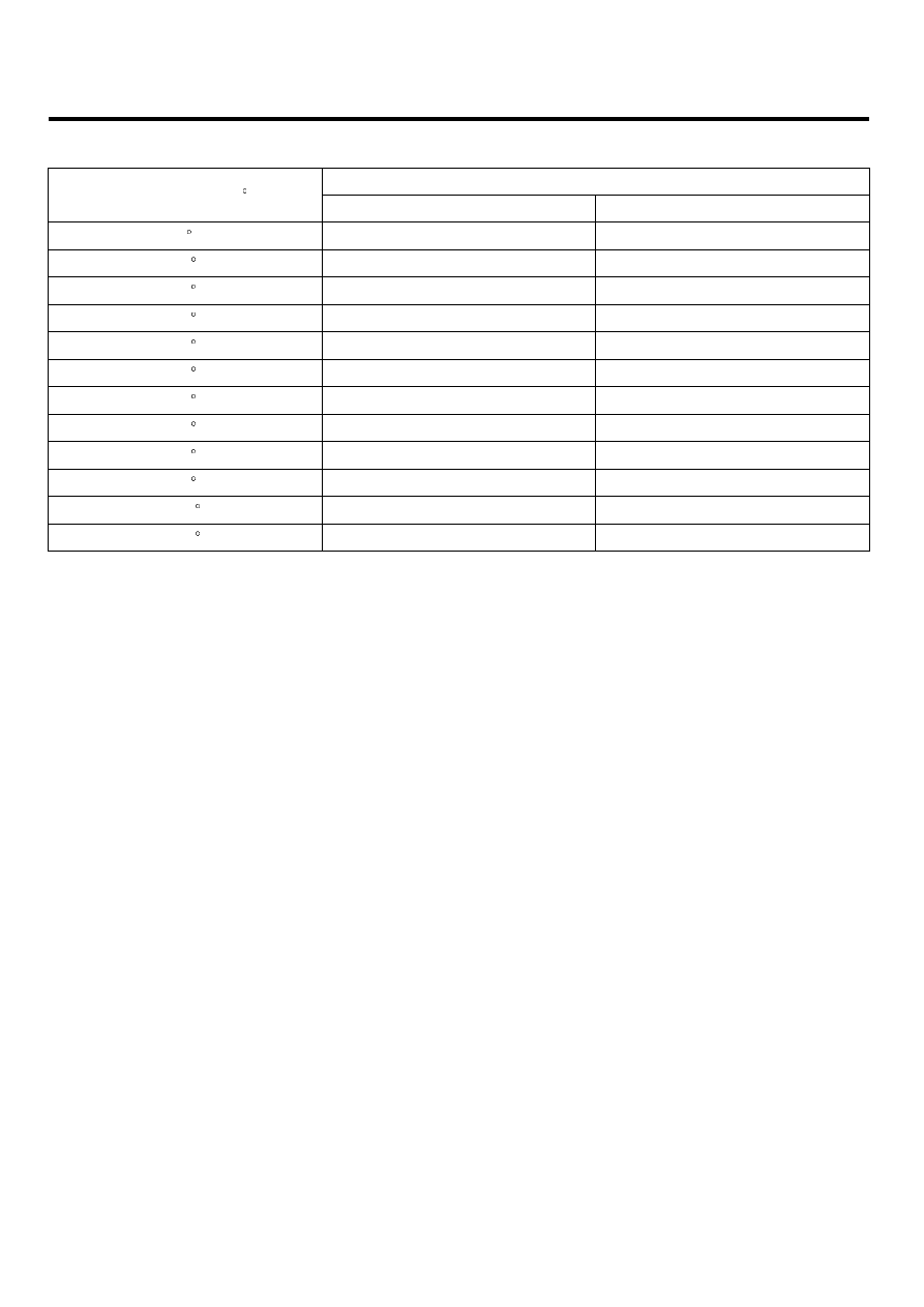
Output voltage(V) [Vref=5.0]

Throttle opening (

)

TPS1

TPS2

0

0.0V

5.0V

10

0.5V

4.5V

20

0.9V

4.1V

30

1.4V

3.6V

40

1.8V

3.2V

50

2.3V

2.7V

60

2.7V

2.3V

70

3.2V

1.8V

80

3.6V

1.4V

90

4.1V

0.9V

100

4.5V

0.5V

110

5.0V

0.0V

DTC TROUBLESHOOTING PROCEDURES

FLA -327

SCHEMATIC DIAGRAM

EF39B8B3

[CIRCUIT DIAGRAM]

[HARNESS CONNECTORS]

[CONNECTION INFORMATION]

ETC MODULE

C86

Terminal

Connected to

Function

1

2

ETC Module (C86)

3

4

PCM C30-B  (16)

TPS 1 Reference Voltage (+5V)

5

6

PCM C30-B (57)

TPS 2 Signal

7

PCM C30-B  (48)

TPS 1 Signal

8

PCM C30-B  (14)

TPS 1 Ground

PCM (C30-B)

PCM

C30-B

1

2

5

6

3

4

7

8

PCM C30-B (2)

ETC Motor [+] Control

PCM C30-B  (58)

TPS 2 Ground

TPS 2 Reference Voltage (+5V)

PCM C30-B (13)

ETC Motor [-] Control

PCM C30-B (1)

1

21

2

22

3

23

4

24

5

25

6

26

7

27

8

28

9

29

10

30

11

31

12

32

13

33

14

34

15

35

16

36

17

37

18

38

19

39

20

40

41

61

42

62

43

63

44

64

45

65

46

66

47

67

48

68

49

69

50

70

51

71

52

72

53

73

54

74

55

75

56

76

57

77

58

78

59

79

60

80

1

2

4


TPS 1

TPS 2

ETC MOTOR

16 - Reference Voltage (+5V)

48 - TPS 1 Signal

14 - GND

6

3

7

13 - Reference Voltage (+5V)

57 - TPS 2 Signal

58 - GND

8

5

2 - ETC Motor [+] 

1 - ETC Motor [-]

M

SCMF16101L

SIGNAL WAVEFORM AND DATA

E24A5BA6

Open the throttle valve by force at IG ON

Hit the accelerator at IG ON

EGRF604Z

FLA -328

FUEL SYSTEM

MONITOR DTC STATUS

E7C113D0

1.

Check DTC Status

1)

Connect scantool to Data Link Connector(DLC).

2)

IG "ON".

3)

Select "Diagnostic Trouble Codes(DTCs)" mode, and then Press F4(DTAL) to check DTC’s information from the
DTCs menu

4)

Read "DTC Status" parameter.

SCMF16159L

5)

Is parameter displayed "Present fault"?

YES

▶ Go to "Terminal and connector inspection" procedure.

NO

▶ Fault is intermittent caused by poor contact in the sensor’s and/or PCM’s connector or was repaired and PCM
memory was not cleared. Thoroughly check connectors for looseness, poor connection, ending, corrosion, con-
tamination, deterioration, or damage. Repair or replace as necessary and go to "Verification of Vehicle Repair"
procedure.

TERMINAL AND CONNECTOR INSPECTION

EBF4C90A

1.

Many malfunctions in the electrical system are caused by poor harness and terminals. Faults can also be caused by
interference from other electrical systems, and mechanical or chemical damage.

2.

Thoroughly check connectors for looseness, poor connection, bending, corrosion, contamination, deterioration, or
damage.

3.

Has a problem been found?

YES

▶ Repair as necessary and go to "Verification of Vehicle Repair" procedure

NO

DTC TROUBLESHOOTING PROCEDURES

FLA -329

▶ Go to "Power Circuit Inspection" procedure.

POWER CIRCUIT INSPECTION

E9ED0C51

1.

IG "OFF" and disconnect TPS connector.

2.

IG "ON" and ENG "OFF"

3.

Measure voltage between terminal 7 of TPS harness connector and chassis ground.

Specification : Approx. 5V

4.

Is the measured voltage within specification ?

YES

▶ Go to "Signal circuit inspection" procedure.

NO

▶ Repair open or short to ground in power harness, and go to "Verification of Vehicle Repair" procedure.

SIGNAL CIRCUIT INSPECTION

E2A4F904

1.

Check short to ground in harness

1)

IG "OFF" and disconnect TPS connector and PCM connector.

2)

Measure resistance between terminal 3 of TPS harness connector and chassis ground.

3)

Measure resistance between terminals 3 and 6(1) of TPS harness connector.

Specification : Infinite

4)

Is the measured resistance within specification?

YES

▶ Go to "Check open in harness" as follows

NO

▶ Repair short to ground in harness, and go to "Verification of Vehicle Repair" procedure.

2.

Check open in harness

1)

IG "OFF" and disconnect TPS connector and PCM connector.

2)

Measure resistance between terminal 3 of TPS harness connector and terminal C30-B (57) of PCM harness
connector.

Specification : Below 1Ω

3)

Is the measured resistance within specification?

YES


Content   ..  563  564  565  566   ..