Hyundai Santa Fe (2006 year). Manual - part 561
FLA -310
FUEL SYSTEM
1
2
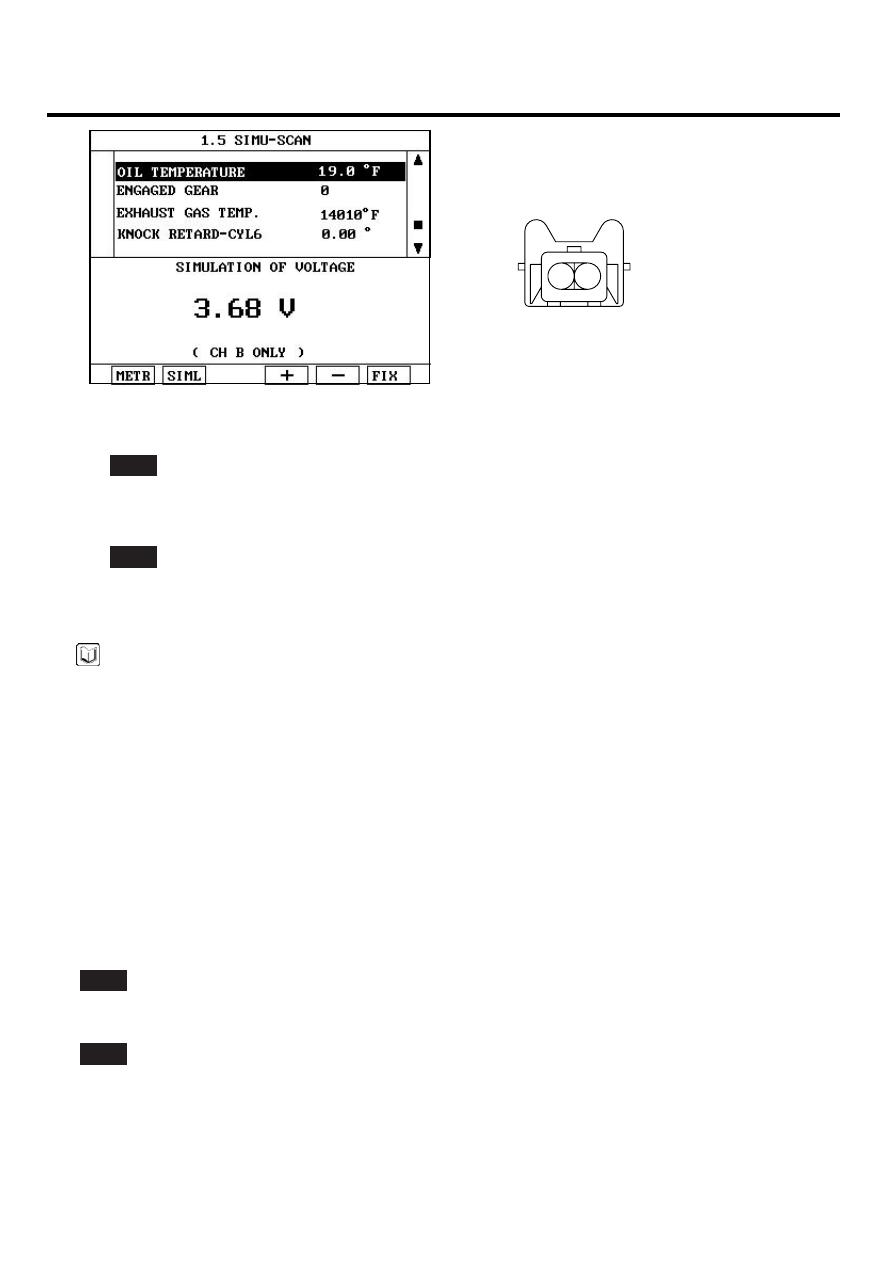
1. OTS Signal
2. OTS Ground
C93
SCMF16242L
5)
Does the OTS signal value changes according to simulation voltage ?
YES
▶ Thoroughly check connectors for looseness, poor connection, bending, corrosion, contamination, deteriora-
tion, or damage. Repair or replace if necessary and go to "Verification of Vehicle Repair" procedure
NO
▶ Substitute with a known - good PCM and check for proper operation. If the problem is corrected, replace PCM
and go to "Verification of Vehicle Repair" procedure.
NOTE
There is a memory reset function on scantool that can erase optional parts automatically detected and memorized
by PCM. After testing PCM on the vehicle, use this function to reuse the PCM on the others
VERIFICATION OF VEHICLE REPAIR
E8F9366F
After a repair, it is essential to verify that the fault has been corrected.
1.
Monitor and record the Freeze Frame Data for the Diagnostic Trouble Code(DTC) which has been diagnosed.
2.
Using a Scantool, Clear the DTCs
3.
Operate the vehicle within conditions noted in the freeze frame data or enable conditions
4.
Monitor that all rediness test have been verified as " Complete "
5.
Are any DTCs present ?
YES
▶ Go to the applicable troubleshoooting procedure.
NO
▶ System is performing to specification at this time.