Hyundai Santa Fe (2006 year). Manual - part 557


  Index      Hyundai     Hyundai Santa Fe - service repair manual 2006 year


Search            


Content   ..  555  556  557  558   ..


Hyundai Santa Fe (2006 year). Manual - part 557


FLA -294

FUEL SYSTEM

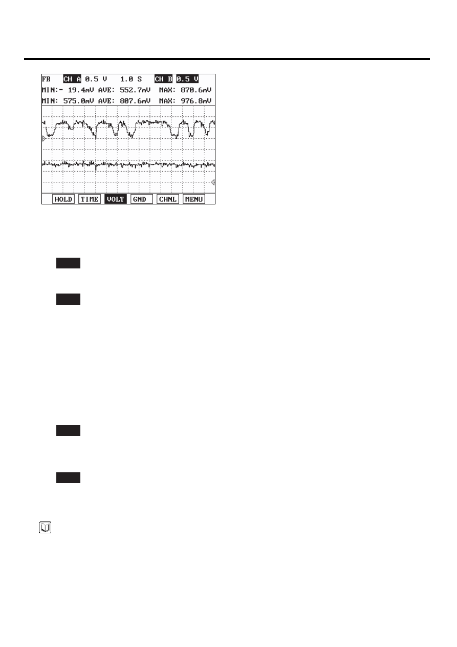
 Fig) Signal waveform of front(the upper) and rear(the lower) HO2S at idle

SCMF16225L

4)

Is the sensor switching properly?

YES

▶ Go to "Check HO2S" as below.

NO

▶ Substitute with a known - good HO2S and check for proper operation.
If the problem is corrected, go to "Verification of Vehicle Repair" procedure.

2.

Check HO2S

1)

IG "OFF" and disconnect HO2S connector.

2)

Check that the HO2S is securely installed.

3)

Check the HO2S for contamination or damage

4)

Is the sensor normal?

YES

▶ Substitute with a known - good PCM and check for proper operation.
If the problem is corrected, go to "Verification of Vehicle Repair" procedure.

NO

▶ Substitute with a known - good HO2S and check for proper operation.
If the problem is corrected, go to "Verification of Vehicle Repair" procedure.

NOTE

There is a memory reset function on scantool that can erase optional parts automatically detected and memorized
by PCM. Before or after testing PCM on the vehicle, use this function to reuse the PCM on the others.

VERIFICATION OF VEHICLE REPAIR

EB601912

Refer to DTC P0157.

DTC TROUBLESHOOTING PROCEDURES

FLA -295

DTC P0171 SYSTEM TOO LEAN (BANK 1)
DTC P0174 SYSTEM TOO LEAN (BANK 2)

GENERAL DESCRIPTION

E0E9D636

In order to provide the best possible combination of drivability, fuel economy and emission control, the ECM uses a closed
loop air/fuel metering system. The ECM monitors the HO2S signal voltage and adjusts fuel delivery based it in closed
loop fuel control. Changes in fuel delivery will be indicated by the long-term and the short-term fuel trim values. The ideal
fuel trim value is around 0%. The ECM will add fuel when the HO2S signal is indicating a lean condition. Additional fuel
is indicated by fuel trim values that are above 0%. The ECM will reduce fuel when the HO2S signal is indicating a rich
condition. Reduction in fuel is indicated by fuel trim values that are below 0%. The DTC relevant to fuel trim will be set
when the amount reaches excessive levels because of a lean or rich condition.

DTC DESCRIPTION

EB85DC59

Checking air-fuel ratio correction value every 0.75 sec. under detecting condition, if an value is within detecting condition
for more than 0.3 sec., PCM sets P0171/P0174. MIL(Malfunction Indication Lamp) turns on when the malfunction lasts
till consecutive 2 driving cycle.

DTC DETECTING CONDITION

E461125D

Item

Detecting Condition

Possible cause

DTC Strategy

• Fuel Trim Limits Exceeded

Enable Conditions

• 550rpm ≤ Engine speed ≤ 4000rpm
• 60℃(140℉) ≤ Engine coolant temperature

≤ 115℃(239℉)

• -10℃(14℉) ≤ Intake air temperature ≤ 60℃(140℉)
• 0 ≤ Throttle position ≤ 80
• 25kPa ≤ Engine load ≤ 90kPa
• 1.5g/s ≤ Intake air flow ≤ 80g/s
• Barometric pressure ≥ 72kPa
• Vehicle speed ≤ 130km/h
• System voltage ≥ 11V
• Feed-back control state
• No other diagnostic fault

Threshold value

• Average of short term fuel trim 〉1.2
• Average of long term fuel trim 〉0.8

Diagnosis Time

• Continuous

(More than 0.3 second failure for every
0.75 second test )

MIL On Condition

• 2 Driving Cycles

• Poor connection
• Relevant sensor/actuator
• Air leakage
• PCM

MONITOR DTC STATUS

EA2D7ED9

1.

Check DTC Status

1)

Connect scantool to Data Link Connector(DLC).

2)

IG "ON".

3)

Select "Diagnostic Trouble Codes(DTCs)" mode, and then Press F4(DTAL) to check DTC’s information from the
DTCs menu

FLA -296

FUEL SYSTEM

4)

Read "DTC Status" parameter.

SCMF16159L

5)

Is parameter displayed "Present fault"?

YES

▶ Go to "Terminal and connector inspection" procedure.

NO

▶ Fault is intermittent caused by poor contact in the sensor’s and/or PCM’s connector or was repaired and PCM
memory was not cleared. Thoroughly check connectors for looseness, poor connection, ending, corrosion, con-
tamination, deterioration, or damage. Repair or replace as necessary and go to "Verification of Vehicle Repair"
procedure.

TERMINAL AND CONNECTOR INSPECTION

E791F73B

1.

Many malfunctions in the electrical system are caused by poor harness and terminals. Faults can also be caused by
interference from other electrical systems, and mechanical or chemical damage.

2.

Thoroughly check connectors for looseness, poor connection, bending, corrosion, contamination, deterioration, or
damage.

3.

Has a problem been found ?

YES

▶ Repair as necessary and go to "Verification of Vehicle Repair" procedure

NO

▶ Go to " System Inspection " procedure.

SYSTEM INSPECTION

E77E6B06

1.

Check air leakage

1)

Visually/physically inspect the air leakage in intake/exhaust system for following items
▶ Vacuum hoses for splits, kinks and improper connections.
▶ Throttle body gasket

DTC TROUBLESHOOTING PROCEDURES

FLA -297

▶ Gasket between intake manifold and cylinder head
▶ Seals between intake manifold and fuel injectors
▶ Exhaust system between HO2S and three way catalyst for air leakage

2)

Has a problem found in this procedure?

YES

▶ Repair or replace it which has a problem, and go to "Verification of Vehicle Repair" procedure.

NO

▶ Go to "Check the fuel line" as follows

2.

Check the fuel line

1)

Check the fuel line for following items
▶ Connector connection state
▶ Damage/ connection state for vacuum hoses connected to fuel line
▶ Bent/ pressed/ twisted fuel line or fuel leakage

2)

Has a problem found in this procedure?

YES

▶ Repair or replace it which has a problem, and go to " Verification of Vehicle Repair" procedure.

NO

▶ Go to "Check fuel pressure" as follows

3.

Check fuel pressure

NOTE

-

Be cautious that Fuel is explosive and an empty fuel tank can still contain explosive gases.When working on fuel
system make sure to supply adequate ventilation to the work area. Do not smoke, and keep sparks and open
flames away.

-

The fuel system remains under pressure when the engine is not running. Release fuel system pressure before
disconnecting any fuel line to reduce the chance of presonal injury or fire damage to vehicle components.

1)

Start the engine and disconnect the fuel pump relay.

2)

Wait until fuel in fuel line is exhausted and the engine stalls.

3)

Turn the ignition switch OFF position.

4)

Install the special service tool for measuring the fuel pressure between the delivery pipe and the fuel feed hose.

5)

Connect the fuel pump relay.

6)

With fuel pressure applied, check the three is no fuel leakage from the fuel pressure gauge or connection part.

7)

Start the engine and measure the fuel pressure at idle.

Specification : 374 ~ 384 kpa (3.82 ~ 3.92 kg/㎠, 54.3 ~ 55.8psi)

8)

Stop the engine and check for a change in the fuel pressure gauge reading.


Content   ..  555  556  557  558   ..