Hyundai Santa Fe (2006 year). Manual - part 540
FLA -226
FUEL SYSTEM
▶ Repair open in harness, and go to "Verification of Vehicle Repair" procedure.
GROUND CIRCUIT INSPECTION
ED915B6F
1.
IG "OFF" and disconnect ECTS connector.
2.
Measure voltage between terminal 3 of ECTS harness connector and chassis ground.
3.
Measure voltage between terminals 1 and 3 of ECTS harness connector.
Specification : Voltage difference between measurement "A" and "B" is below 200mV.
4.
Is the measured voltage within specification?
YES
▶ Go to "Component Inspection" procedure.
NO
▶ Repair open or contact resistance in harness, and go to "Verification of Vehicle Repair" procedure.
COMPONENT INSPECTION
E86B0A34
1.
Check ECTS
1)
IG "OFF" and disconnect ECTS connector.
2)
Measure resistance between terminals 1 and 3 of ECTS connector.(Component side)
SPECIFICATON :
Temp. (℃/℉)
Resistance (kΩ )
Temp. (℃/℉)
Resistance (kΩ )
-40(-40)
48.14
40(104)
1.15
-20(-4)
14.13 ~ 16.83
60(140)
0.59
0(32)
5.79
80(176)
0.32
20(68)
2.31 ~ 2.59
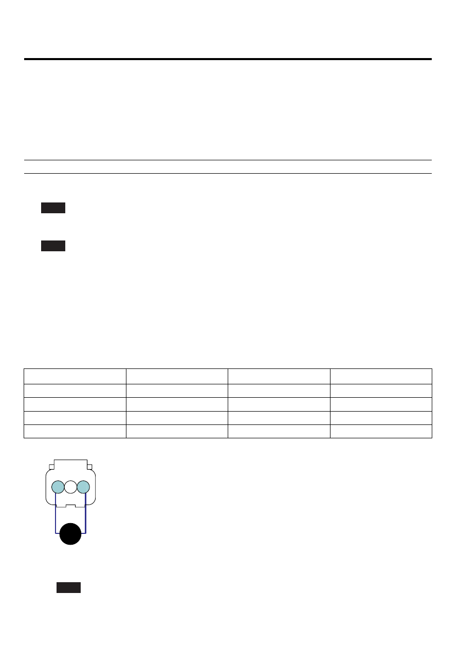
C04
1. ECTS Ground
2. To Gauge
3. ECTS Signal
Ω
3
2
1
SCMF16211L
3)
Is the measured resistance within specification?
YES
▶ Go to "Check PCM" as follows.