Hyundai Santa Fe (2006 year). Manual - part 498
 

  Index      Hyundai     Hyundai Santa Fe - service repair manual 2006 year


Search            


Content   ..  496  497  498  499   ..


Hyundai Santa Fe (2006 year). Manual - part 498


FLA -58

FUEL SYSTEM

CIRCUIT DIAGRAM

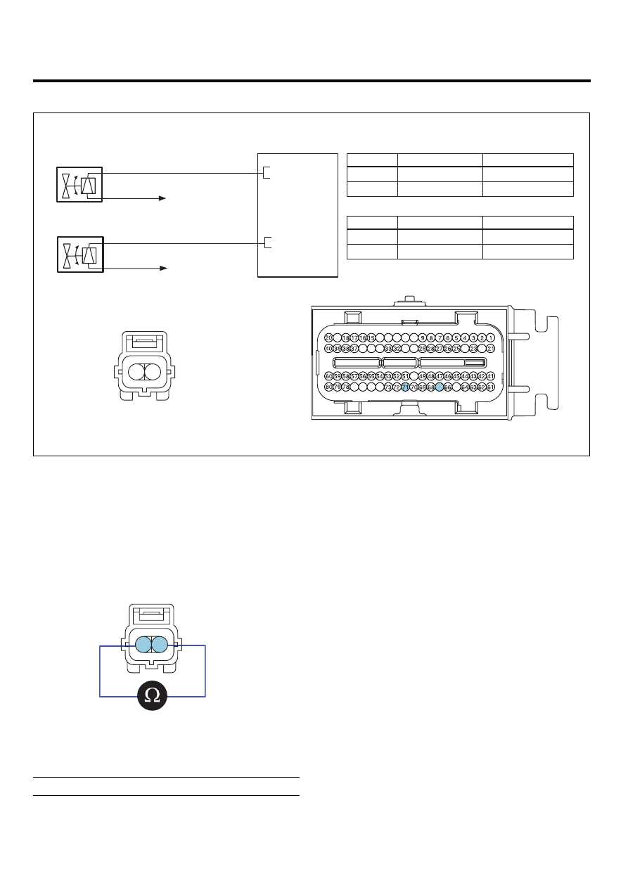
VIS VALVE #1,2

PCM

C96-1,2

1

2

PCM C30-A (71)

Battery voltage (B+)

VIS Valve #1 control

Main Relay

[CIRCUIT DIAGRAM]

[HARNESS CONNECTORS]

[CONNECTION INFORMATION]

Terminal

Connected to

Function

C30-A

19

14 13 12 11

31

34

35

36

30

10

24

22

65

67

50

74

75

76

77

71 - VIS Valve #1

PCM (C30-A)

VIS VALVE #1 

(C96-1)

Main Relay

2

1

1

2

Control

67 - VIS Valve #2

VIS VALVE #2 

(C96-2)

Main Relay

2

1

Control

1

2

PCM C30-A (67)

Battery voltage (B+)

VIS Valve #2 control

Main Relay

Terminal

Connected to

Function

VIS VALVE #1 

VIS VALVE #2

SCMF16121L

COMPONENT INSPECTION

1.

Turn ignition switch OFF.

2.

Disconnect VIS Valve connector.

3.

Measure resistance between VIS Valve #1,2 termi-
nals 1 and 2.

2

1

SCMF16122L

4.

Check that the resistance is within the specification.

Specification: Refer to SPECIFICATION.

GASOLINE ENGINE CONTROL SYSTEM

FLA -59

ACCELERATOR POSITION
SENSOR (APS)

INSPECTION

EFDE8560

FUNCTION AND OPERATION PRICIPLE

APS 1

APS 2

Pedal Stroke

Stroke (mm)

Output Voltage 

(V

)

5.0

3.85 ~ 4.35

1.93 ~ 2.18

0.7 ~ 0.8

0.29 ~ 0.46

C.T

W.O.T

2.5

APS

SCMF16123L

Accelerator Position Sensor (APS) is installed on the ac-
celerator pedal module and detects the rotation angle of
the accelerator pedal. The APS is one of the most im-
portant sensors in engine control system, so it consists of
the two sensors which adapt individual sensor power and
ground line. The second sensor monitors the first sensor
and its output voltage is half of the first one. If the ratio
of the sensor 1 and 2 is out of the range (approximately
1/2), the diagnostic system judges that a malfunction has
occurred.

SPECIFICATION

Output Voltage (V) [Vref = 5.0V]

Pedal Position

APS1

APS2

C.T

0.7 ~ 0.8V

0.29 ~ 0.46V

W.O.T

3.85 ~ 4.35V

1.93 ~ 2.18V

Item

Sensor Resistance

APS1

0.7 ~ 1.3㏀ at 20℃ (68℉)

APS2

1.4 ~ 2.6㏀ at 20℃ (68℉)

FLA -60

FUEL SYSTEM

CIRCUIT DIAGRAM

APS

E02

1

2

PCM C30-A (54)

APS 1 Signal

3

4

PCM C30-A (48)

APS 2 Reference Voltage (+5V)

APS 2 Ground

5

PCM C30-A (55)

APS 1 Ground

6

PCM C30-A (59)

APS 1 Reference Voltage (+5V)

PCM C30-A (57)

PCM (C30-A)

[CIRCUIT DIAGRAM]

[HARNESS CONNECTORS]

[CONNECTION INFORMATION]

Terminal

Connected to

Function

APS 2 Signal

PCM C30-A (49)

PCM

C30-A

19

14 13 12 11

31

34

35

36

30

10

24

22

65

67

50

74

75

76

77

5

2

6

APS (E02)

APS 1

APS 2

59 - Reference Voltage (+5V)

54 - APS 1 Signal

55 - GND

4

1

3

57 - Reference Voltage (+5V)

49 - APS 2 Signal

48 - GND

SCMF16124L

COMPONENT INSPECTION

1.

Connect a scantool on Diagnoisis Link Connector
(DLC).

2.

Start engine and check output voltages of APS 1 and
2 at C.T and W.O.T.

SPECIFICATION

Output Voltage (V)

Condition

APS1

APS2

C.T

0.70 ~ 0.80

0.29 ~ 0.46

W.O.T

3.85 ~ 4.35

1.93 ~ 2.18

3.

Turn ignition switch OFF and disconnect the scantool
from the DLC.

4.

Disconnect APS connector and measure resistance
between APS terminals 5 and 6 (APS 1).

Specification: Refer to SPECIFICATION.

5.

Disconnect APS connector and measure resistance
between APS terminals 3 and 4 (APS 2).

SCMF16125L

Specification: Refer to SPECIFICATION.

GASOLINE ENGINE CONTROL SYSTEM

FLA -61

POWERTRAIN CONTROL
MODULE (PCM)

POWERTRAIN CONTROL MODULE

(PCM)

E75F1EFA

1.

HARNESS CONNECTOR

C30-A

C30-B

19

14 13 12 11

31

34

35

36

30

10

24

22

65

67

50

74

75

76

77

1

21

2

22

3

23

4

24

5

25

6

26

7

27

8

28

9

29

10

30

11

31

12

32

13

33

14

34

15

35

16

36

17

37

18

38

19

39

20

40

41

61

42

62

43

63

44

64

45

65

46

66

47

67

48

68

49

69

50

70

51

71

52

72

53

73

54

74

55

75

56

76

57

77

58

78

59

79

60

80

SCMF16126L

2.

TERMINAL FUNCTION

CONNECTOR [C30-A]

Pin

No.

Description

Connected to

1

2nd CAN [High]

Multi-Purpose Check Connector

2

2nd CAN [Low]

Multi-Purpose Check Connector

3

-

4

-

5

-

6

-

7

-

8

-

9

-

10

Power Steering Switch signal input

Power Steering Switch

11

-

12

-

13

Clutch Switch signal input

Clutch Switch

14

-

15

Alternator load signal input

Alternator

16

Cruise Switch ground

Cruise Switch

17

-

18

A/C switch "ON" signal input

A/C Switch

19

-

20

-


Content   ..  496  497  498  499   ..