Hyundai Santa Fe (2006 year). Manual - part 496
FLA -50
FUEL SYSTEM
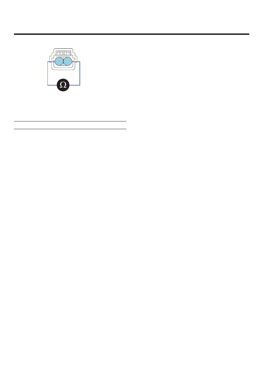
1
2
SCMF16114L
4.
Check that the resistance is within the specification.
Specification: Refer to SPECIFICATION.
|
|
|
FLA -50 FUEL SYSTEM 1 2 SCMF16114L 4. Check that the resistance is within the specification. Specification: Refer to SPECIFICATION. |