Hyundai Santa Fe (2006 year). Manual - part 494


  Index      Hyundai     Hyundai Santa Fe - service repair manual 2006 year


Search            


Content   ..  492  493  494  495   ..


Hyundai Santa Fe (2006 year). Manual - part 494


FLA -42

FUEL SYSTEM

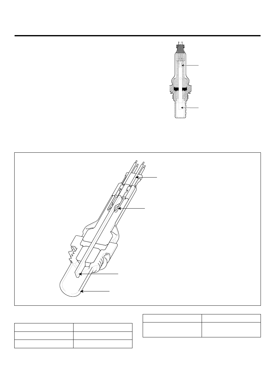
HEATED OXYGEN SENSOR
(HO2S)

INSPECTION

E1DADE40

FUNCTION AND OPERATION PRICIPLE

Heated Oxygen Sensor (HO2S) consists of zirconium and
alumina and is installed on upstream and downstream of
the Manifold Catalyst Converter (MCC). After it compares
oxygen consistency of the atmosphere with the exhaust
gas, it transfers the oxygen consistency of the exhaust gas
to the PCM. When A/F ratio is rich or lean, it generates ap-
proximately 1V or 0V respectively. In order that this sen-
sor normally operates, the temperature of the sensor tip
is higher than 370℃ (698℉). So it has a heater which is
controlled by the PCM duty signal. When the exhaust gas
temperature is lower than the specified value, the heater
warms the sensor tip.

Terminal

Sensing Element

EGRF247A

Cable

Terminal Interface

Element Tip

Shield

EGRF248A

SPECIFICATION

A/F Ratio

Output Voltage (V)

RICH

0.80 ~ 0.92

LEAN

0.1

Item

Specification

Heater Resistance (Ω )

3.0 ~ 4.0Ω at 21℃

(69.8℉)

GASOLINE ENGINE CONTROL SYSTEM

FLA -43

WAVEFORM

HO2S (

 1) 

HO2S (

 1)

HO2S (

 2) 

HO2S (

 2)

HO2S (

 1)

HO2S (

 2)

LGLG002E

FLA -44

FUEL SYSTEM

CIRCUIT DIAGRAM

HO2S [Bank 1/Sensor 1]
HO2S [Bank 2/Sensor 1]

PCM

C91-1,2

C30-B

PCM (C30-B)

HO2S [B1/S1] (C91-1)

1

2

1

21

2

22

3

23

4

24

5

25

6

26

7

27

8

28

9

29

10

30

11

31

12

32

13

33

14

34

15

35

16

36

17

37

18

38

19

39

20

40

41

61

42

62

43

63

44

64

45

65

46

66

47

67

48

68

49

69

50

70

51

71

52

72

53

73

54

74

55

75

56

76

57

77

58

78

59

79

60

80

Battery Voltage (B+)

Main Relay

3

4

PCM C30-B (30)

HO2S [B1/S1] Signal

Sensor ground

PCM C30-B (49)

Main Relay

3

4

1

2

49 - HO2S [B1/S1] Signal

30 - GND

70 - Heater [B1/S1] Control

HO2S [B2/S1] (C91-2)

Main Relay

3

4

1

2

51 - HO2S [B2/S1] Signal

28 - GND

67 - Heater [B2/S1] Control

HO2S [B1/S2] (C91-3)

Main Relay

3

4

1

2

50 - HO2S [B1/S2] Signal

31 - GND

74 - Heater [B1/S2] Control

HO2S [B2/S2] (C91-4)

Main Relay

3

4

1

2

52 - HO2S [B2/S2] Signal

29 - GND

73 - Heater [B2/S2] Control

1

2

3

4

PCM C30-B (28)

HO2S [B2/S1] Signal

Sensor ground

PCM C30-B (51)

Battery Voltage (B+)

Main Relay

PCM C30-B (67)

Heater

 [B2/S1] Control

1

2

3

4

PCM C30-B (31)

HO2S [B1/S2] Signal

Sensor ground

PCM C30-B (50)

Battery Voltage (B+)

Main Relay

PCM C30-B (74)

Heater

 [B1/S2] Control

1

2

3

4

PCM C30-B (29)

HO2S [B2/S2] Signal

Sensor ground

PCM C30-B (52)

Battery Voltage (B+)

Main Relay

PCM C30-B (73)

Heater

 [B2/S2] Control

[CIRCUIT DIAGRAM]

[HARNESS CONNECTORS]

[CONNECTION INFORMATION]

Terminal

Connected to

Function

Terminal

Connected to

Function

Terminal

Connected to

Function

Terminal

Connected to

Function

HO2S [B1/S1]

HO2S [B2/S1]

HO2S [B1/S2]

HO2S [B2/S2]

PCM C30-B (70)

Heater

 [B1/S1] Control

HO2S [Bank 1/Sensor 2]
HO2S [Bank 2/Sensor 2]

C91-3,4

2

1

4

3

1

2

3

4

SCMF16110L

COMPONENT INSPECTION

1.

Check signal waveform of HO2S using a scantool.

Specification: Refer to "waveform".

2.

Disconnet the HO2S connector.

3.

Measure resistance between HO2S heater terminals
3 and 4.

GASOLINE ENGINE CONTROL SYSTEM

FLA -45

2

1

4

3

1

2

3

4

SCMF16111L

4.

Check that the resistance is within the specification.

Specification: Refer to SPECIFICATION.


Content   ..  492  493  494  495   ..