Hyundai Santa Fe (2006 year). Manual - part 463
FL -462
FUEL SYSTEM
DTC DETECTING CONDITION
E5E34C80
Item
Detecting Condition
Possible Cause
DTC Strategy
• Voltage monitoring
Enable Conditions
• Engine running
Threshold Value
• (Case 1) VSCA real value is higher than VSCA
target value by more than 5%.
• (Case 2) VSCA real value is lower than VSCA
target value by more than 7%.
• (Case 3) Variable swirl valve operating motor is
mechanically stuck during operation
• (Case 4) Variable swirl valve operating motor is
mechanically stuck during learning ’closing’ process.
Diagnostic Time
• (Case 1,2,3) 1 sec.
• (Case 4) 3 sec.
Fuel cut
NO
EGR Off
(Case1,2)
:
NO
(Case3,4)
:
YES
Fuel Limit
NO
Fail Safe
Check
Lamp
NO
• Swirl valve opened at
variable swirl control
actuator failure
• Variable swirl valve
shaft stuck
• Variable swirl valve link
device problem
• Variable swirl valve position
sensor component
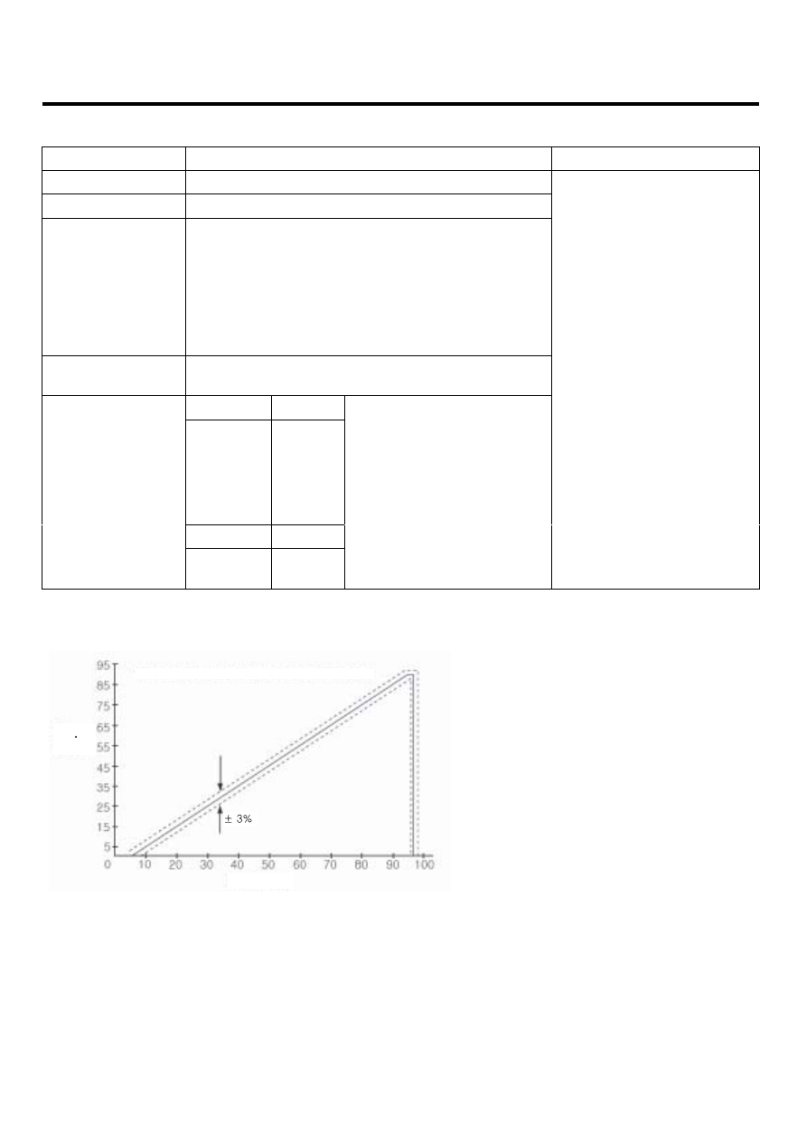
SPECIFICATION
E5DFC840
Variable swirl control actuator characteristic curve
Degree
[ ]
Duty [%]
LFIG510A