Hyundai Santa Fe (2006 year). Manual - part 457


  Index      Hyundai     Hyundai Santa Fe - service repair manual 2006 year


Search            


Content   ..  455  456  457  458   ..


Hyundai Santa Fe (2006 year). Manual - part 457


FL -438

FUEL SYSTEM

Fig.1

Fig.2

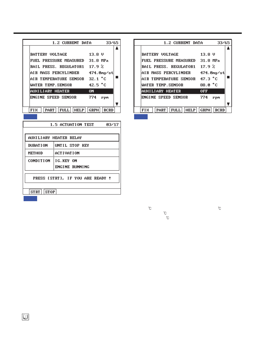
Fig.1)  "AUXILIARY HEATER" operates only when Intake air temp. is below 5

 and Engine coolant temp. is below 70

.

           "ON" state of  "AUXILIARY HEATER" lasts till Engine coolant temp. reaches 70

.  

Fig.2)  "AUXILIARY HEATER" turns "OFF" as soon as engine coolant temp. reaches 70

.

Fig.3) If it is difficult to cool engine when current condition does not meat  "AUXILIARY HEATER" operating condition, 
          check relay operation using "ACTUATION TEST" function on the Scantool.

Fig.3

SCMFL6347L

TERMINAL AND CONNECTOR INSPECTION

EE5C6C40

1.

Electrical systems consist of a lot of harness and connectors, poor connection of terminals can cause various prob-
lems and damge of component.

2.

Perform checking procedure as follows.

1)

Check damage of harness and terminals : Check terminals for contact resistance, corrosion and deformation.

2)

Check connecting condition of ECM and component connector : Check terminal seperation, damage of locking
device and connecting condition between terminal and wiring.

NOTE

Disconnect the pin which requires checking at male connector and insert it to the terminal at female connector for
checking connecting condition. ( after checking, reconnect the pin at correct position. )

3.

Is the problem found?

DTC TROUBLESHOOTING PROCEDURES

FL -439

YES

Repair the trouble causing part and go to "Verification of Vehicle Repair".

NO

Go to "Power Circuit Inspection".

POWER CIRCUIT INSPECTION

E3849909

1.

Check HOT AT ALL TIMES power circuit voltage

1)

IG KEY "OFF", ENGINE "OFF"

2)

Disconnect PTC heater relay #1.

3)

Measure the voltage of PTC heater relay #1 connector terminal 1.

Specification : 11.5V~13.0V

4)

Is the measured voltage within the specification?

YES

Go to "2. Check IG KEY "ON" power circuit voltage" as follows.

NO

Repair FUSIBLE LINK BOX 40A PTC HEATER #1 FUSIBLE LINK and related circuit and go to "Verification

of Vehicle Repair".

2.

Check IG KEY "ON" power circuit voltage

1)

IG KEY "OFF", ENGINE "OFF"

2)

Disconnect PTC heater relay #1.

3)

IG KEY "ON"

4)

Measure the voltage of PTC heater relay #1 connector terminal 4.

Specification : 11.5V~13.0V

5)

Is the measured voltage within the specification?

YES

Go to "Control Circuit Inspection".

NO

Repair E/R FUSE & RELAY BOX 15A SENSOR #2 FUSE and related circuit and go to "Verification of

Vehicle Repair".

CONTROL CIRCUIT INSPECTION

EF7657E4

1.

Check control circuit monitoring voltage

FL -440

FUEL SYSTEM

1)

IG KEY "ON", ENGINE "OFF".

2)

Disconnect PTC heater relay #1.

3)

IG KEY "ON"

4)

Measure the voltage of PTC heater relay #1connector terminal 2.

Specification : 8.0V~10.0V

5)

Is the measured voltage within the specification?

YES

Go to "2. Check open in control circuit" as follows.

NO

Repair short to battery in control circuit and go to "Verification of Vehicle Repair".

2.

Check open in control circuit

1)

IG KEY "OFF", ENGINE "OFF"

2)

Disconnect PTC heater relay #1 and ECM connector.

3)

Check continuity between PTC heater relay #1 connector terminal 2 and ECM connector (C230-K) terminal 94.

specification : Continuity ( below 1.0

)

4)

Is the measured resistance within the specification?

YES

Go to "3. Check short to ground in control circuit" as follows.

NO

Repair open in control circuit and go to "Verification of Vehicle Repair".

3.

Check short to ground in control circuit

1)

IG KEY "OFF", ENGINE "OFF"

2)

Disconnect PTC heater relay #1 and ECM connector.

3)

Measure the resistance of PTC heater relay #1 connector terminal 2.

specification : Discontinuity ( Infinite

)

4)

Is the measured resistance within the specification?

YES

Go to "Component Inspection".

NO

DTC TROUBLESHOOTING PROCEDURES

FL -441

Repair short to ground in control circuit and go to "Verification of Vehicle Repair".

COMPONENT INSPECTION

EFFBE24C

1.

Check PTC heater relay #1 component coil resistance

1)

IG KEY "OFF", ENGINE "OFF".

2)

Disconnect PTC heater relay #1.

3)

Measure the resistance of PTC heater relay #1 component coil.

Specification : 80±5

Ω

(20

)

30

86

87

85

EGNG007M

4)

Is the measured resistance within the specification?

YES

Go to "2. Check PTC heater relay #1 component operation" as follows.

NO

Replace PTC heater relay #1 and go to "Verification of Vehicle Repair".

2.

Check PTC heater relay #1 component operation

1)

IG KEY "OFF", ENGINE "OFF"

2)

Disconnect PTC heater relay #1.

3)

Supplies random B+ and ground to coil sides of PTC heater relay #1. ( terminal 85, 86)

4)

Check continuity between PTC heater relay #1 terminal 30 and terminal 87.

specification : When power is supplied : Continuity ( below 1.0

)

When power is not supplied : Discontinuity ( Infinite

)


Content   ..  455  456  457  458   ..