Hyundai Santa Fe (2006 year). Manual - part 432


  Index      Hyundai     Hyundai Santa Fe - service repair manual 2006 year


Search            


Content   ..  430  431  432  433   ..


Hyundai Santa Fe (2006 year). Manual - part 432


FL -338

FUEL SYSTEM

COMPONENT INSPECTION

ED9E4369

1.

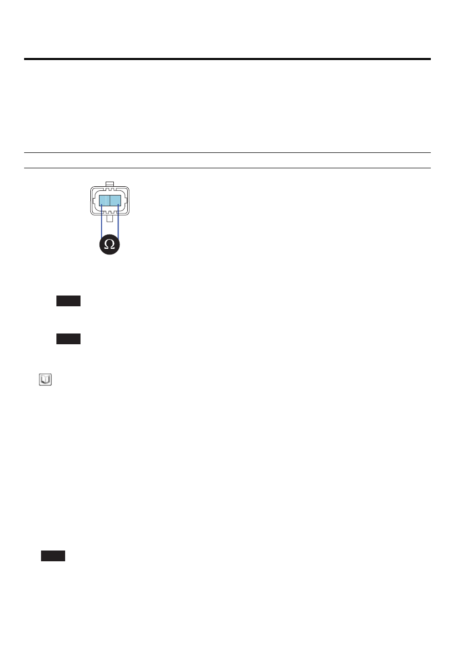
Check injector component resistance

1)

IG KEY "OFF", ENGINE "OFF".

2)

Disconnect injector connector.

3)

Measure the resistance between injector component terminal 1 and 2.

Specification : 0.33

Ω

(20

)

1

2

EGNG008I

4)

Is the measured resistance(of injector solenoid) within the specification?

YES

Go to "Verification of Vehicle Repair".

NO

Replace injector and go to "Verification of Vehicle Repair".

NOTE

Replacing injectors, peculiar IQA code of each injector should be inputted to ECM
Perform this process using "INJECTOR CORRECTION" function on scantool, Refer to P1670, P1671 for more de-
tailed information.

VERIFICATION OF VEHICLE REPAIR

E62E741F

After a repair, it is essential to verify that the fault is corrected.

1.

After connecting Scantool select "DIAGNOSTIC TROUBLE CODES(DTCs)" mode.

2.

Clear recorded DTC using Scantool.

3.

Drive the vehicle within DTC "Enable conditions" in "General information".

4.

After selecting "DIAGNOSTIC TROUBLE CODES(DTCs)" mode and check if DTC is recorded again.

5.

Are any DTCs recorded ?

YES

Go to the DTC guide of recorded NO. in Scantool.

DTC TROUBLESHOOTING PROCEDURES

FL -339

NO

System operates within specification.

FL -340

FUEL SYSTEM

DTC P0642 SENSOR REFERENCE VOLTAGE "A" CIRCUIT LOW

GENERAL DESCRIPTION

EC7DA3AD

ECM is activated by power supply. Signals from several sensors, such as CKPS and APS, is inputted to ECM. Comparing
inputted siganals with control LOGIC saved at micro controller and EEPROM, ECM controlls engine as actuating injectors,
solenoids and relays. To guarantee accurate control, ECM performs SELF TEST, DIAGNOSIS of several sensors and
actuators. And if serious trouble which affects vehicle performance occurrs, ECM sets DTCs.At certain cases, ECM shuts
down whole systems in order to prevent dangerous situation due to incorrect control.

DTC DESCRIPTION

E391557F

P0642 is set when the voltage below 4.7V - minimum voltage of sensor power supply 1 generates from ECM - is detected
for more than 0.1 sec.. This code is due to the short to ground in sensor power circuit or the voltage problem inside of
ECM.

DTC DETECTING CONDITION

EA9F074F

Item

Detecting Condition

Possible Cause

DTC Strategy

• Voltage monitoring

Enable Conditions

• IG KEY "ON"

Threshold Value

• when the voltage is below the minimum voltage

of sensor power supply. ( below 4.7V )

Diagnostic Time

• 0.1 sec.

Fuel cut

NO

EGR Off

NO

Fuel Limit

YES

Fail Safe

Check

Lamp

NO

• MAFS power supply circuit
• APS 1 power supply circuit
• ECM component

SPECIFICATION

E3B931C6

Sensor power 1

Sensor power 2

Sensor power 3

MAFS, APS 1

4830mV~5158mV

RPS, APS 2,BPS

4830mV~5158mV

A/C pressure transducer,VSA

position Sensor

4830mV~5158mV

DTC TROUBLESHOOTING PROCEDURES

FL -341

SCHEMATIC DIAGRAM

E82B0251

APS

C256

1

2

ECM C230-K (9)

APS 1 Signal

3

4

ECM C230-K (45)

APS 2 Reference Voltage (+5V)

APS 2 Ground

5

ECM C230-K (30)

APS 1 Ground

6

ECM C230-K (8)

APS 1 Reference Voltage (+5V)

ECM C230-K (31)

ECM (C230-K)

[CIRCUIT DIAGRAM]

[HARNESS CONNECTORS]

[CONNECTION INFORMATION]

Terminal

Connected to

Function

APS 2 Signal

ECM C230-K (46)

ECM

C230-A

C230-K

1

2

4

3

6

5

8 7

12

13

16

17

18

23 22

20

21

19

27 26 25 24

28

29

30

14

9

10

11

15

33 32 31

34

37

41

42

40 39 38

35

36

43

44

47 46

49 48

50

53

56

58 57

54

51

52

55

59

60
45

1

30 29

31

32

38

39

36

37

35

33

34

40

42 41

46 45 44 43

48 47

50 49

2

3

4

6

5

8

7

12 11 10 9

13

14

15

18 17

19

16

22

25

27 26

23

20

21

24

28

51

75 74
53 52

73

79 78 77 76

80

81

83 82

84

86 85

87

89 88

90

92 91

93

94

57

69 68

70

71

64

54

55

56

61

58

59

60

63 62

65

66

67

72

1

2

3

4

5

6

5

2

4

APS (C256)

APS 1

APS 2

45 - Reference Voltage (+5V)

9 - APS 1 Signal

30 - GND

6

3

1

46 - Reference Voltage (+5V)

31 - APS 2 Signal

8 - GND

SCMFL6123L


Content   ..  430  431  432  433   ..