Hyundai Santa Fe (2006 year). Manual - part 415
FL -270
FUEL SYSTEM
SPECIFICATION
E7EC0A4A
Sensor Type
Output Signal
Characteristic
Air Gab
Low RPM Minimum
Detecting Voltage
High RPM Minimum
Detecting Voltage
Hall effect type
0V~5V Digital signal
output
1.25mm
below 2.0V
above 3.8V
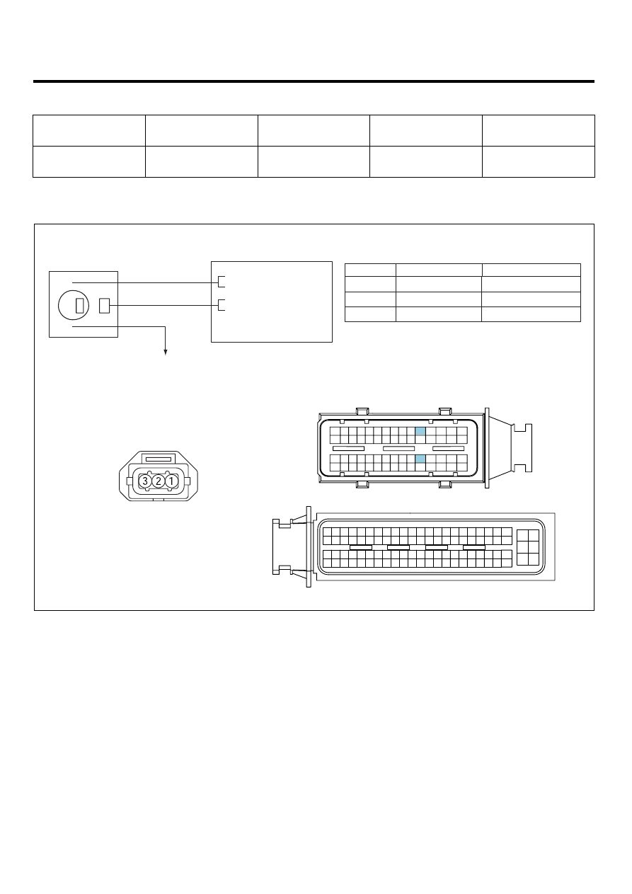
SCHEMATIC DIAGRAM
E9AA72A7
CMPS
C210
ECM (C230-A)
CMPS (C210)
1
2
ECM C230-A (50)
CMPS Signal
Battery Voltage
3
ECM C230-A(20)
GND
Main Relay
20 - GND
3
2
50 - CMPS
[Bank 1] Signal
1
[CIRCUIT DIAGRAM]
[HARNESS CONNECTORS]
[CONNECTION INFORMATION]
Terminal
Connected to
Function
Main Relay
ECM
C230-A
C230-K
1
2
4
3
6
5
8 7
12
13
16
17
18
23 22
20
21
19
27 26 25 24
28
29
30
14
9
10
11
15
33 32 31
34
37
41
42
40 39 38
35
36
43
44
47 46
49 48
50
53
56
58 57
54
51
52
55
59
60
45
1
30 29
31
32
38
39
36
37
35
33
34
40
42 41
46 45 44 43
48 47
50 49
2
3
4
6
5
8
7
12 11 10 9
13
14
15
18 17
19
16
22
25
27 26
23
20
21
24
28
51
75 74
53 52
73
79 78 77 76
80
81
83 82
84
86 85
87
89 88
90
92 91
93
94
57
69 68
70
71
64
54
55
56
61
58
59
60
63 62
65
66
67
72
SCMFL6120L