Hyundai Santa Fe (2006 year). Manual - part 390


  Index      Hyundai     Hyundai Santa Fe - service repair manual 2006 year


Search            


Content   ..  388  389  390  391   ..


Hyundai Santa Fe (2006 year). Manual - part 390


FL -170

FUEL SYSTEM

DTC P0117 ENGINE COOLANT TEMPERATURE CIRCUIT LOW INPUT
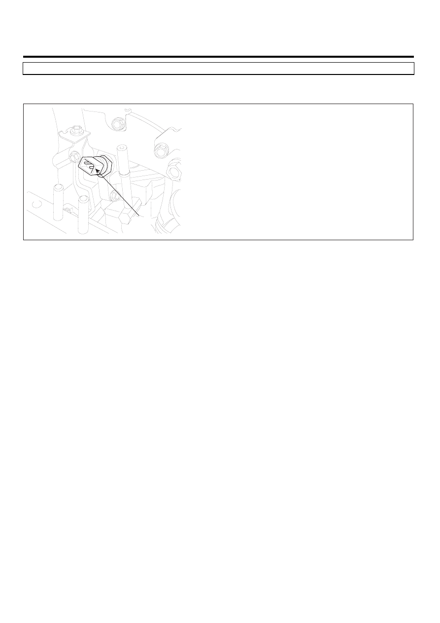
COMPONENT LOCATION

E356AAFA

ECTS

LFIG385A

GENERAL DESCRIPTION

E0EDC9B9

Engine Coolant Temperature Sensor(ECTS), installed in coolant line, senses engine coolant temperature.With the infor-
mation about engine coolant temperature, ECM performs fuel injection quantity correction, cooling fan control and glow
relay operating duration control.Especially, because ECTS signal is main variable of fuel injection quantity correction when
engine is cold, sensor trouble makes starting engine difficult when engine is cold.If engine is running when ECTS is out
of order, ECM considers engine coolant temperature as 80

. And during cranking, ECM considers engine coolant tem-

perature as -10

. Besides, cooling fan, which is controlled based on ECTS signal, operates at HIGH-MODE to prevent

engine from being overheated and supplementary heater is deactivated.

DTC DESCRIPTION

E89F57FF

P0117 is set when the voltage below 0.083V - minimum output voltage of ECTS - is detected for more than 2.0 sec. This
code is due to short to ground in signal circuit.

DTC TROUBLESHOOTING PROCEDURES

FL -171

DTC DETECTING CONDITION

E23715EB

Item

Detecting Condition

Possible Cause

DTC Strategy

• Voltage monitoring

Enable Conditions

• IG KEY "ON"

Threshold Value

• Output signal below the minimum value.(

below 0.083 V )

Diagnostic Time

• 2.0 sec.

Fuel cut

NO

EGR Off

YES

Fuel Limit

NO

Fail Safe

Check

Lamp

NO

• A/C condensor fan control

operation based on engine
coolant temperature
inhibited.

• PTC heater inhibited.
• Cooling fan is fixed at

HIGH-MODE.

• During engine operation :

temperature is fixed at 80

• At cold and cranking :

temperature is fixed at -10

• ECTS circuit
• ECTS component

SPECIFICATION

EDD59882

Temperature

-40

-20

0

20

40

Resistance

48.14

15.48±1.35

5.790

2.45±0.14

1.148

Temperature

60

80

100

110

120

Resistance

0.586

0.322

0.188

0.147±0.002

0.116

FL -172

FUEL SYSTEM

SCHEMATIC DIAGRAM

E4689316

ECTS

C204

1

2

Cluster

-

ECM C230-A (58)

3

ECM C230-A (41)

ECTS Signal

ECM (C230-A)

ECTS (C204)

3

2

1

58 - ECTS Signal

Cluster

41 - GND

[CIRCUIT DIAGRAM]

[HARNESS CONNECTORS]

[CONNECTION INFORMATION]

Terminal

Connected to

Function

Sensor ground

ECM

C230-A

C230-K

1

2

4

3

6

5

8 7

12

13

16

17

18

23 22

20

21

19

27 26 25 24

28

29

30

14

9

10

11

15

33 32 31

34

37

41

42

40 39 38

35

36

43

44

47 46

49 48

50

53

56

58 57

54

51

52

55

59

60
45

1

30 29

31

32

38

39

36

37

35

33

34

40

42 41

46 45 44 43

48 47

50 49

2

3

4

6

5

8

7

12 11 10 9

13

14

15

18 17

19

16

22

25

27 26

23

20

21

24

28

51

75 74
53 52

73

79 78 77 76

80

81

83 82

84

86 85

87

89 88

90

92 91

93

94

57

69 68

70

71

64

54

55

56

61

58

59

60

63 62

65

66

67

72

1

2

3

SCMFL6119L

SIGNAL WAVEFORM AND DATA

E635F8BF

Fig.1

Fig.1) ECTS output signal at 80

.The higher temperature rises, the lower signal voltage becomes.

LFIG387A

MONITOR SCANTOOL DATA

ED4A0ECB

1.

Connect Scantool to Data Link Connector (DLC).

DTC TROUBLESHOOTING PROCEDURES

FL -173

2.

Warm engine up to normal operating temperature.

3.

Turn "OFF" electrical devices and A/C.

4.

Monitor "ECTS" parameter on the Scantool.

Specification : Current enigne coolant temperature is displayed.

Fig.1

Fig.1) Check if 1) incorrect value is displayed 2) coolant temperature is fixed at 80

 suddenly during driving 

      3)coolant temperature is fixed at -10

 when turning IG KEY "ON". That coolant temperature is fixed at -10

 or 80


      means failure of ECTS. To prevent overheat of engine due to ECTS , if ECTS fails, cooling fan operates continuously.

SCMFL6227L

TERMINAL AND CONNECTOR INSPECTION

E633DB0B

1.

Electrical systems consist of a lot of harness and connectors, poor connection of terminals can cause various prob-
lems and damge of component.

2.

Perform checking procedure as follows.

1)

Check damage of harness and terminals : Check terminals for contact resistance, corrosion and deformation.

2)

Check connecting condition of ECM and component connector : Check terminal seperation, damage of locking
device and connecting condition between terminal and wiring.

NOTE

Disconnect the pin which requires checking at male connector and insert it to the terminal at female connector for
checking connecting condition. ( after checking, reconnect the pin at correct position. )

3.

Is the problem found?

YES

Repair the trouble causing part and go to "Verification of Vehicle Repair".

NO

Go to "Signal Circuit Inspection ".

SIGNAL CIRCUIT INSPECTION

EA1B1C97

1.

Check signal circuit voltage


Content   ..  388  389  390  391   ..