Hyundai Santa Fe (2006 year). Manual - part 368
FL -82
FUEL SYSTEM
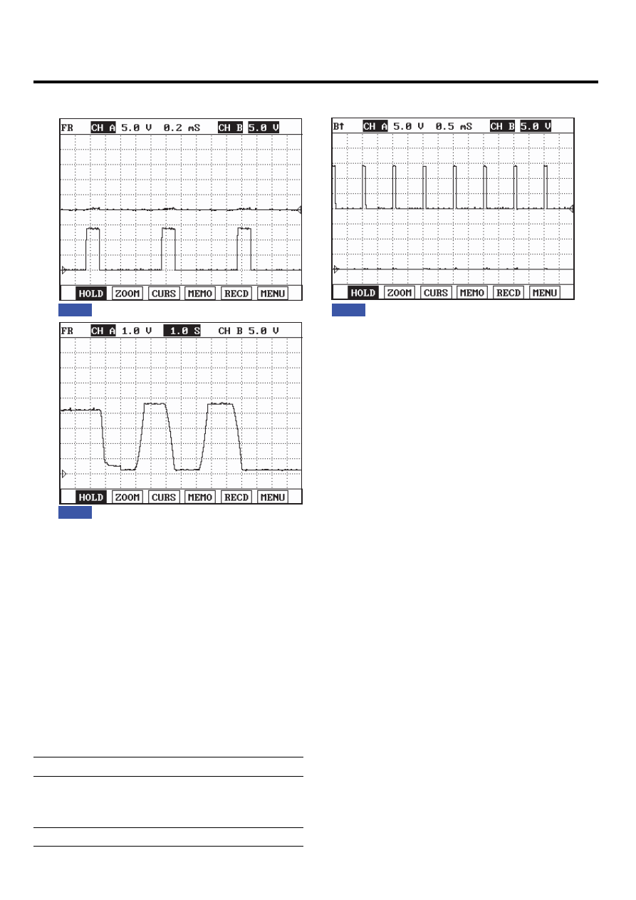
SIGNAL WAVEFORM
Fig.1
Fig.2
Fig.1) Waveform when variable swirl valve closed at idle. Terminal 5 is (+) and 4 is (-).
Fig. 2) Waveform when variable swirl valve opened at above 3000RPM. Terminal 5 is (-) and 4 is (+).
Fig. 3) Waveform of variable swirl control actuator motor position sensor at the point of turning engine OFF.
4.3V at swirl valve closed and 0.3V at swirl valve opened. Swirl valve is opened and closed twice at engine "OFF".
Fig.3
EFQG512A
COMPONENT INSPECTION
1.
Turn ignition switch OFF.
2.
Disconnect the electric EGR control valve connector.
3.
Check that swirl valve is stuck by foreign material.
4.
Measure resistance between motor (+) and (-) control
terminals.
Specification: Refer to "SPECIFICATION".
5.
Measure resistance between voltage supply terminal
and ground terminal of position sensor.
Specification: Refer to "SPECIFICATION".