Hyundai Santa Fe (2006 year). Manual - part 363
FL -62
FUEL SYSTEM
CRANKSHAFT POSITION SENSOR
(CKPS)
INSPECTION
E39BA5C3
FUNCTION AND OPERATION PRINCIPLE
Piston position on combustion chamber is the substantial
to define the starting of injection timing. All engine pistons
are connected to crankshaft by connecting rod. Sensor
on crankshaft can supply the informations concerning all
piston positions, revolution speed is defined by revolution
perminute of crankshaft. Prior input variable is determined
at ECM by using signal induced from crankshaft position
sensor.
CKPS
EFQG046A
SPECIFICATION
Items
Specification
Coil Resistance (
Ω
)
774 ~ 946
Ω
[20
℃
(68
℉
)]
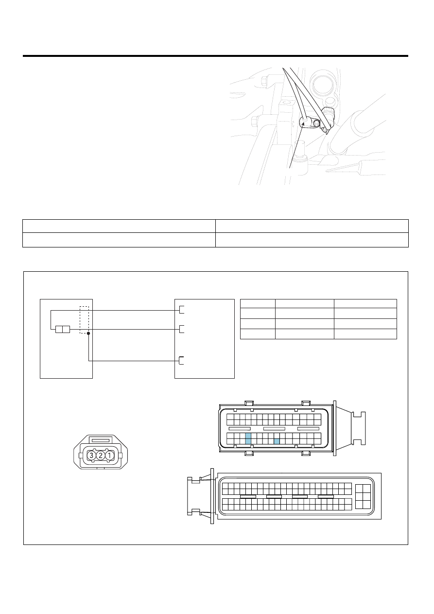
CIRCUIT DIAGRAM
CKPS
C201
ECM (C230-A)
CKPS (C201)
1
2
ECM C230-A (12)
Sensor Shield
CKPS [-]
Signal
3
ECM C230-A (27)
CKPS [+]
Signal
ECM C230-A (7)
27 - CKPS [+]
12 - CKPS [-]
7 - Shield
3
2
1
S
N
[CIRCUIT DIAGRAM]
[HARNESS CONNECTORS]
[CONNECTION INFORMATION]
Terminal
Connected to
Function
ECM
C230-A
C230-K
1
2
4
3
6
5
8 7
12
13
16
17
18
23 22
20
21
19
27 26 25 24
28
29
30
14
9
10
11
15
33 32 31
34
37
41
42
40 39 38
35
36
43
44
47 46
49 48
50
53
56
58 57
54
51
52
55
59
60
45
1
30 29
31
32
38
39
36
37
35
33
34
40
42 41
46 45 44 43
48 47
50 49
2
3
4
6
5
8
7
12 11 10 9
13
14
15
18 17
19
16
22
25
27 26
23
20
21
24
28
51
75 74
53 52
73
79 78 77 76
80
81
83 82
84
86 85
87
89 88
90
92 91
93
94
57
69 68
70
71
64
54
55
56
61
58
59
60
63 62
65
66
67
72
SCMFL6121L