Hyundai Santa Fe (2006 year). Manual - part 346


  Index      Hyundai     Hyundai Santa Fe - service repair manual 2006 year


Search            


Content   ..  344  345  346  347   ..


Hyundai Santa Fe (2006 year). Manual - part 346


TIMING SYSTEM

EMA -95

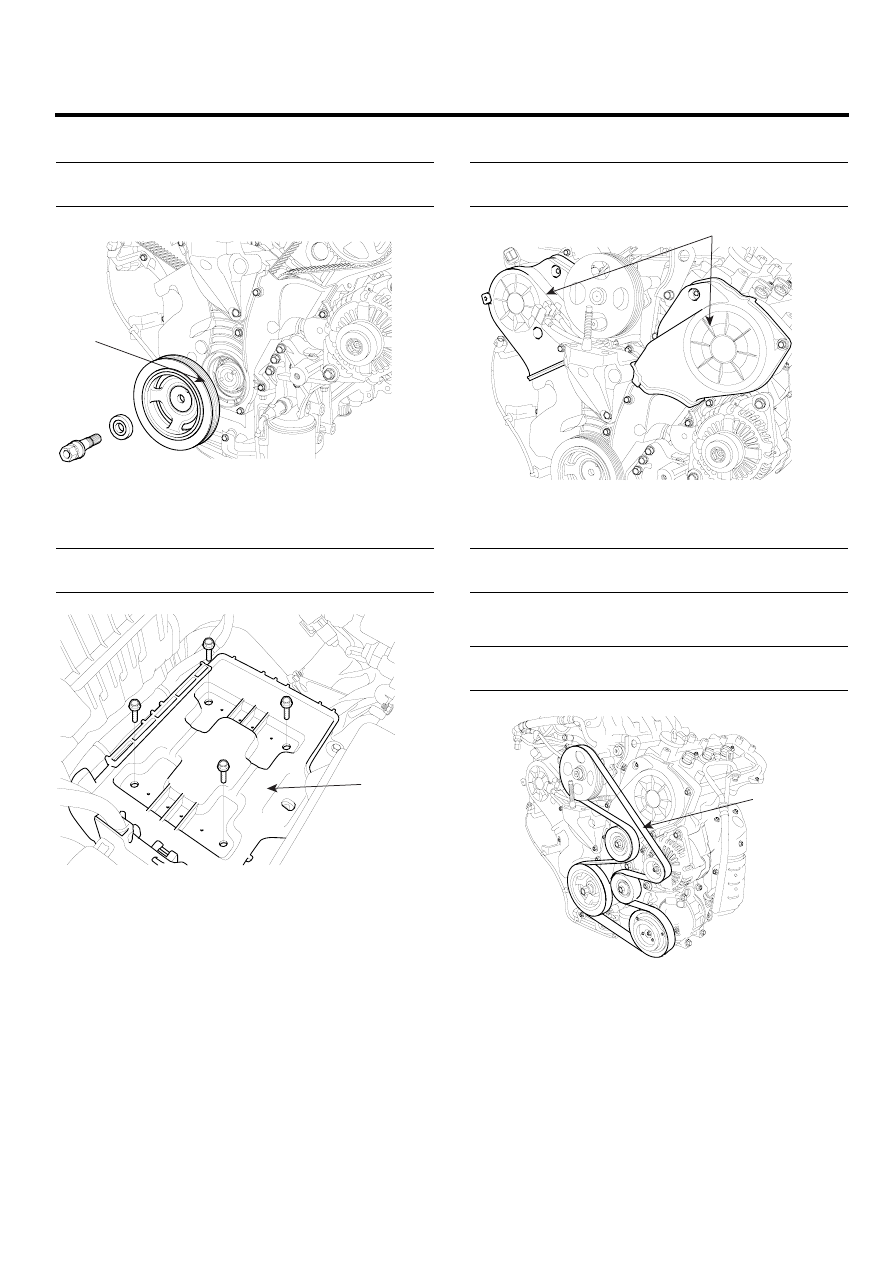
10. Install the crankshaft damper pulley(A).

Tightening torque
166.7 ~ 176.5Nm(17.0 ~ 18.0kgf.m, 123.0 ~ 130.2lb-ft)

A

KCBF109A

11. Install the engine mounting bracket(A).

Tightening torque
63.7 ~ 83.4Nm(6.5 ~ 8.5kgf.m, 47.0 ~ 61.5lb-ft)

A

SCMEM6007L

12. Install the timing belt upper cover(A).

Tightening torque
9.8 ~ 11.8Nm(1.0 ~ 1.2kgf.m, 7.2 ~ 8.7lb-ft)

A

KCBF106A

13. Install the drive belt tensioner(C).

Tightening torque
34.3 ~ 53.9Nm(3.5 ~ 5.5kgf.m, 25.3 ~ 39.8lb-ft)

14. Install the drive belt idler and the drive belt(A).

Tightening torque
34.3 ~ 53.9Nm(3.5 ~ 5.5kgf.m, 25.3 ~ 39.8lb-ft)

A

KCBF105A

15. Install the right side cover.

16. Install the front right wheel and tire.

17. Install the engine cover.

EMA -96

ENGINE (G6EA - GSL 2.7)

ENGINE AND TRANSAXLE
ASSEMBLY

REMOVAL

E73C468F

CAUTION

• Use fender covers to avoid damaging painted

surfaces.

• To avoid damage, unplug the wiring connec-

tors carefully while holding the connector
portion.

NOTE

• Mark all wiring and hoses to avoid misconnec-

tion.

1.

Remove the air duct and the battery(A) after discon-
necting the terminals(B) from the battery.

B

A

SCMEM6006L

2.

Remove the engine cover.

3.

Remove the intake air hose and air cleaner assembly.

1)

Disconnect the MAF connector(A).

2)

Disconnect the breather hose(B) from air cleaner
hose.

3)

Remove the intake air hose and air cleaner as-
sembly(C).

4)

Disconnect the PCM connectors(D).

A

C

D

B

SCMEM6004L

D

LDLG061A

4.

Remove the battery tray(A) while recovering refriger-
ant.

A

SCMEM6007L

ENGINE AND TRANSAXLE ASSEMBLY

EMA -97

5.

Remove the upper radiator hose(A) and lower radiator
hose(B).

A

B

LDLG008A

6.

Remove the transaxle oil cooler hoses(A/T vehicles
only).

7.

Remove the fuel inlet hose(A) from the delivery pipe.

A

LDLG062A

8.

Disconnect the engine wiring harness connectors.

1)

Disconnect the No.1/No.2 knock sensor con-
nectors(A,B), the oil pressure switch connec-
tor(C), the ignition coil harness(D) and the No.1
VIS(Variable Induction System) connector(E).

A

B

C

D

E

LDLG005A

2)

Disconnect the bank 1 front/rear O2 sensor con-
nectors(A).

A

KCBF160A

3)

Disconnect the injection connectors(A,B,C), the
ground lines(D), the condensor connector(E) and
the Ignition coil connectors(F).

C

F

D

B

E

A

LDLG060A

EMA -98

ENGINE (G6EA - GSL 2.7)

4)

Disconnect the injection harness connector(A),
the No.2 VIS(Variable Induction System) con-
nector(B), the No.1/No.2 OCV(Oil Control Valve)
connectors(C,D) and the OTS(Oil Temperature
Sensor) connector(E).

A

C

B

D

E

LDLG006A

5)

Disconnect the MAPS(Manifold Absolute Pres-
sure

Sensor)

connector(A),

the

ETC(Elec-

tronic Throttle Control) connector(B) and the
PCSV(Purge Control Solenoid Valve) connec-
tor(C).

A

B

LDLG034A

C

LDLG035A

6)

Disconnect the generator connector(A) and the
air conditioning compressor connector(B).

A

B

KCBF151A

7)

Disconnect the bank 2 CMP sensor connector(A)
and the WTS(Water Temperature Sensor) con-
nector(B).

A

B

KCBF155A


Content   ..  344  345  346  347   ..