Hyundai Santa Fe (2006 year). Manual - part 302
EM -10
ENGINE (D4EB - DIESEL 2.2)
SPEICAL SERVICE TOOLS
E764F48B
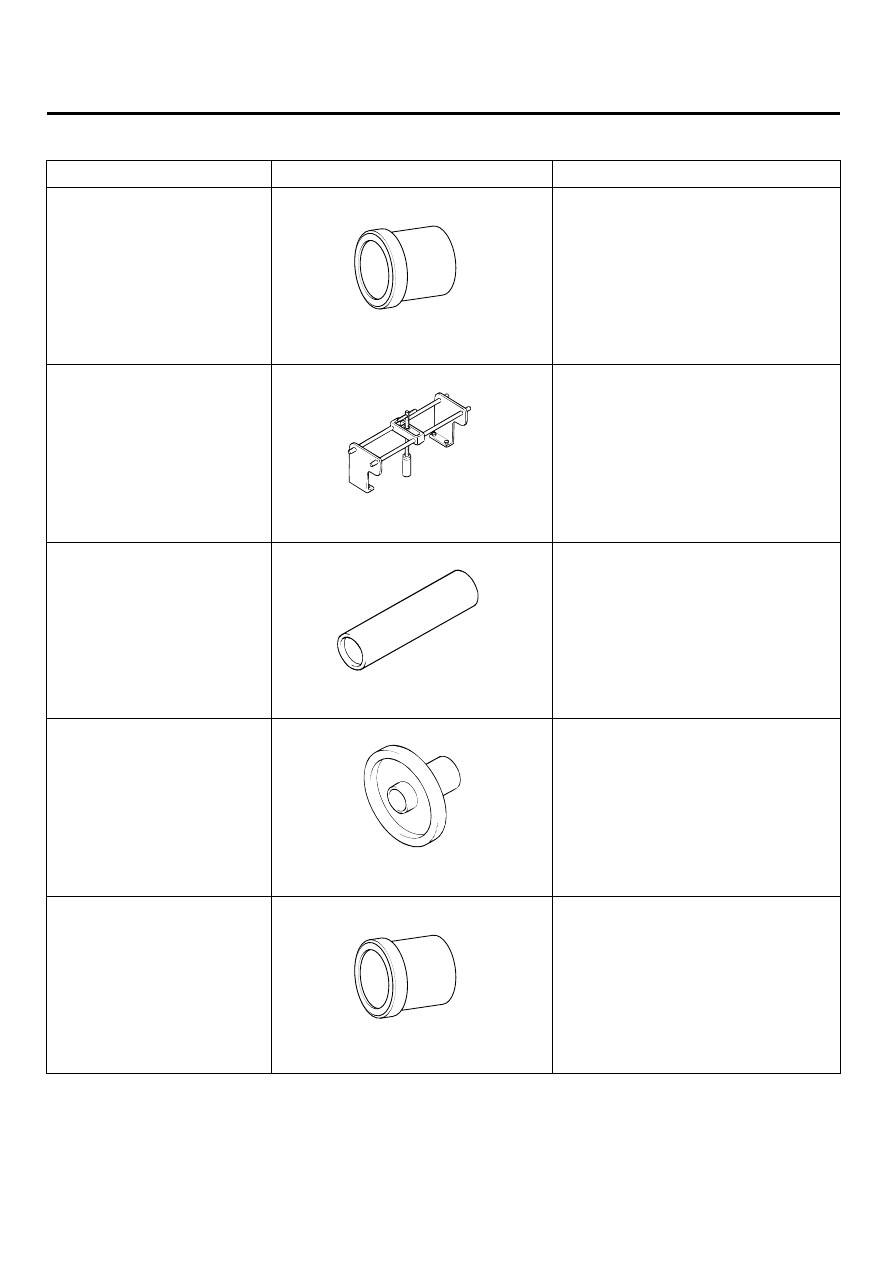
Tool (Number and name)
Illustration
Use
Camshaft oil seal installer
(09212-27100)
ACIE003A
Installation of the camshaft oil seal
Valve spring compressor
(09222-27300)
ACIE004A
Removal and installation of intake
and exhaust valves
Valve stem oil seal installer
(09222-27200)
ACIE005A
Installation of valve stem oil seals
Crankshaft rear oil seal installer
(09231-27000)
ACIE006A
Installation of the crankshaft real oil seal
Front case oil seal installer
(09231-27100)
ACIE003A
Installation of the front case oil seal