Hyundai Santa Fe (2006 year). Manual - part 298


  Index      Hyundai     Hyundai Santa Fe - service repair manual 2006 year


Search            


Content   ..  296  297  298  299   ..


Hyundai Santa Fe (2006 year). Manual - part 298


STARTING SYSTEM

EEA -33

REMOVAL

E2DAEAB6

1.

Disconnect the battery negative cable.

2.

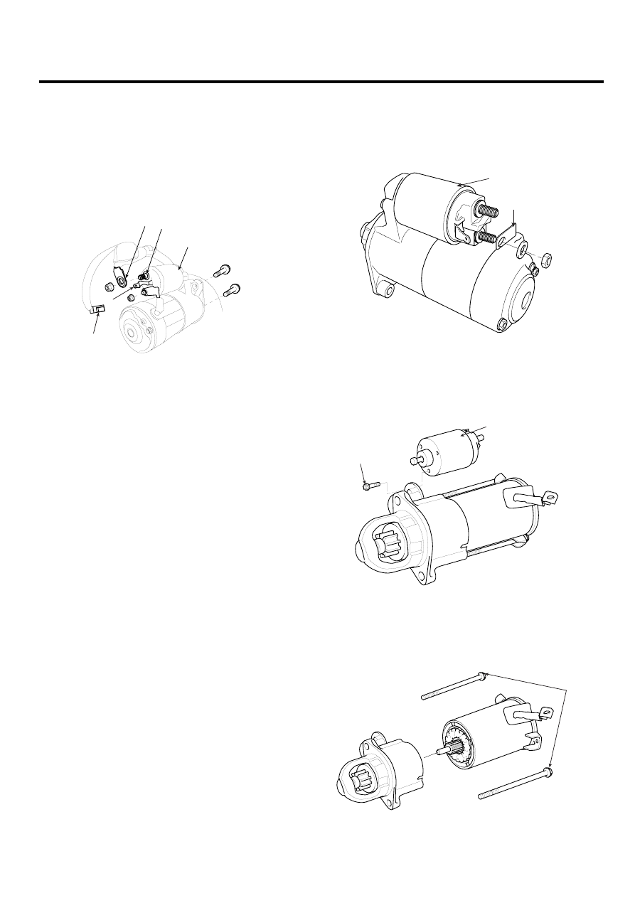
Disconnect the starter cable (A) from the B terminal
(B) on the solenoid (C), then disconnect the connector
(D) from the S terminal (E).

D

E

A

B

C

ABGE024A

3.

Remove the 2 bolts holding the starter, then remove
the starter.

4.

Installation is the reverse of removal.

5.

Connect the battery negative cable to the battery.

DISASSEMBLY

EBCFFF4B

1.

Disconnect the M-terminal (A) on the magnet switch
assembly (B).

B

A

EBKD011C

2.

After loosening the 3 screws (A), detach the magnet
switch assembly (B).

A

B

KBRF010A

3.

Loosen the through bolts (A).

A

KBRF011A

EEA -34

ENGINE ELECTRICAL SYSTEM

4.

Remove the brush holder assembly (A), yoke (b) and
armature (C).

C

B

A

KBRF012A

5.

Remove the shield (A) and packing (B).

A

B

KBRF014A

6.

Remove the lever plate (A) and lever packing (B).

A

B

EBKD011H

7.

Disconnect the planet gear (A).

A

EBKD011I

8.

Disconnect the planet shaft assembly (A) and lever
(B).

A

B

EBKD011J

9.

Press the stop ring (A) using a socket (B).

A

B

EBKD011K

STARTING SYSTEM

EEA -35

10. After removing the stopper (A) using stopper pliers

(B).

B

A

EBKD011L

11. Disconnect the stop ring (A), overrunning clutch (B),

internal gear (C) and planet shaft (D).

A

C

B

D

EBKD011M

12. Reassembly is the reverse of disassembly.

NOTE

Using a suitable pulling tool (A), pull the overrunning
clutch stop ring (B) over the stopper (C).

A

C

B

EBKD011O

EEA -36

ENGINE ELECTRICAL SYSTEM

INSPECTION

E6EB24DE

ARMATURE INSPECTION AND TEST

1.

Remove the starter.

2.

Disassemble the starter as shown at the beginning of
this procedure.

3.

Inspect the armature for wear or damage from con-
tact with the permanent magnet. If there is wear or
damage, replace the armature.

EBKD012A

4.

Check the commutator (A) surface. If the surface is
dirty or burnt, resurface with emery cloth or a lathe
within the following specifications, or recondition with
#500 or #600 sandpaper (B).

B

A

EBKD012B

5.

Measure the commutator (A) runout.

• If the commutator runout is within the service

limit, check the commutator for carbon dust or
brass chips between the segments.

• If the commutator run out is not within the service

limit, replace the armature.

Commutator runout
Standard (New): 0.02mm (0.0008in.) max
Service limit: 0.05mm (0.0020in.)

A

EBKD012D

6.

Check the mica depth (A). If the mica is too high (B),
undercut the mica with a hacksaw blade to the proper
depth. Cut away all the mica (C) between the com-
mutator segments. The undercut should not be too
shallow, too narrow, or v-shaped (D).

Commutator mica depth
Standard (New) : 0.5 mm (0.0197 in.)
Limit : 0.2mm (0.0079 in.)

B

D

C

A

EBKD012E


Content   ..  296  297  298  299   ..