Hyundai Santa Fe (2006 year). Manual - part 295
CHARGING SYSTEM
EEA -21
REGULATED VOLTAGE TEST
The purpose of this test is to check that the electronic volt-
age regulator controls voltage correctly.
PREPARATION
1.
Prior to the test, check the following items and correct
if necessary.
Check that the battery installed on the vehicle is fully
charged. The battery checking method is described
in the section "Battery".
Check the alternator drive belt tension. The belt ten-
sion check method is described in the section "Inspect
drive belt".
2.
Turn ignition switch to "OFF".
3.
Disconnect the battery ground cable.
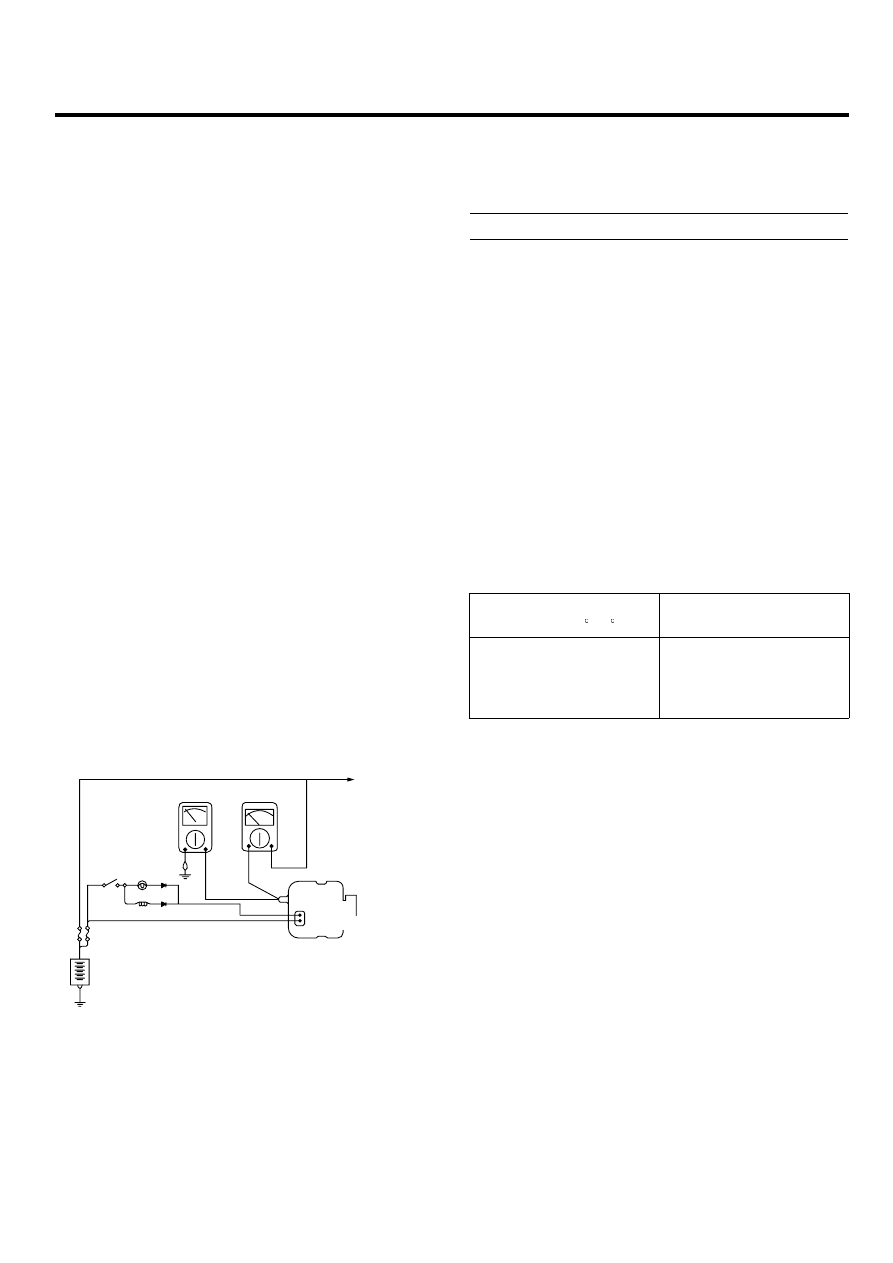
4.
Connect a digital voltmeter between the "B" terminal
of the alternator and ground. Connect the (+) lead
of the voltmeter to the "B" terminal of the alternator.
Connect the (-) lead to good ground or the battery (-)
terminal.
5.
Disconnect the alternator output wire from the alter-
nator "B" terminal.
6.
Connect a DC ammeter (0 to 150A) in series between
the "B" terminal and the disconnected output wire.
Connect the (-) lead wire of the ammeter to the dis-
connected output wire.
7.
Attach the engine tachometer and connect the battery
ground cable.
Voltmeter
Ammeter
Check engine
L
Ioad
S or DUMMY
EBRF020A
TEST
1.
Turn on the ignition switch and check to see that the
voltmeter indicates the following value.
Voltage: Battery voltage
If it reads 0V, there is an open circuit in the wire be-
tween the alternator "B" terminal and the battery and
the battery (-) terminal.
2.
Start the engine. Keep all lights and accessories off.
3.
Run the engine at a speed of about 2,500 rpm and
read the voltmeter when the alternator output current
drops to 10A or less
RESULT
1.
If the voltmeter reading agrees with the value listed in
the regulating voltage table below, the voltage regula-
tor is functioning correctly. If the reading is other than
the standard value, the voltage regulator or the alter-
nator is faulty.
REGULATING VOLTAGE TABLE
Voltage regulator ambient
temperature C ( F)
Regulating voltage (V)
-20 (-4)
20 (68)
60 (140)
80 (176)
14.2 ~ 15.4
14.0 ~ 15.0
13.7 ~ 14.9
13.5 ~ 14.7
2.
Upon completion of the test, reduce the engine speed
to idle, and turn off the ignition switch.
3.
Disconnect the battery ground cable.
4.
Remove the voltmeter and ammeter and the engine
tachometer.
5.
Connect the alternator output wire to the alternator
"B" terminal.
6.
Connect the battery ground cable.