Hyundai Santa Fe (2006 year). Manual - part 294


  Index      Hyundai     Hyundai Santa Fe - service repair manual 2006 year


Search            


Content   ..  292  293  294  295   ..


Hyundai Santa Fe (2006 year). Manual - part 294


CHARGING SYSTEM

EEA -17

CHARGING SYSTEM

DESCRIPTION

ECC3DBD3

The charging system included a battery, an alternator with
a built-in regulator, and the charging indicator light and
wire.
The Alternator has built-in diodes, each rectifying AC cur-
rent to DC current.
Therefore, DC current appears at alternator "B" terminal.
In addition, the charging voltage of this alternator is regu-
lated by the battery voltage detection system.
The alternator is regulated by the battery voltage detec-
tion system. The main components of the alternator are
the rotor, stator, rectifier, capacitor brushes, bearings and
V-ribbed belt pulley. The brush holder contains a built-in
electronic voltage regulator.
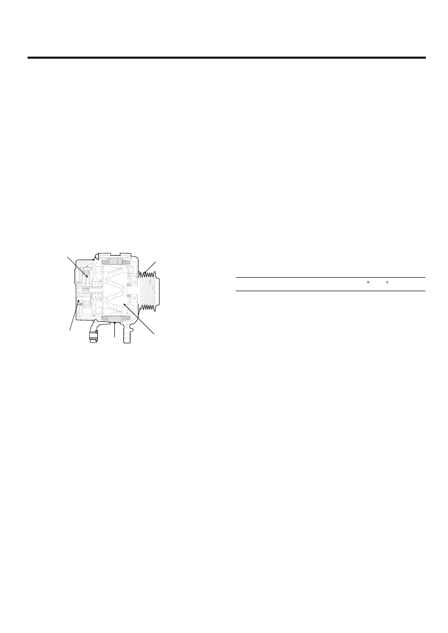
Drive belt pulley

Brush

Rectifler

Stator

Rotor

LBKG001B

ON-VEHICLE INPECTION

E87FA4FF

CAUTION

• Check that the battery cables are connected

to the correct terminals.

• Disconnect the battery cables when the bat-

tery is given a quick charge.

• Never disconnect the battery while the engine

is running.

CHECK BATTERY VOLTAGE

1.

If 20 minutes have not passed since the engine was
stopped, turn the ignition switch ON and turn on the
electrical system (headlamp, blower motor, rear de-
fogger etc.) for 60 seconds to remove the surface
charge.

2.

Turn the ignition switch OFF and turn off the electrical
systems.

3.

Measure the battery voltage between the negative (-)
and positive (+) terminals of the battery.

Standard voltage : 12.5 ~ 12.9V at 20 C(68 F)

If the voltage is less than specification, charge the
battery.

CHECK THE BATTERY TERMINALS AND FUSES

1.

Check that the battery terminals are not loose or cor-
roded.

2.

Check the fuses for continuity.

EEA -18

ENGINE ELECTRICAL SYSTEM

INSPECT DRIVE BELT

Visually check the belt for excessive wear, frayed cords
etc.
If any defect has been found, replace the drive belt.

NOTE

Cracks on the rib side of a belt are considered accept-
able. If the belt has chunks missing from the ribs, it
should be replaced.

EBKD004B

VISUALLY CHECK ALTERNATOR WIRING AND
LISTEN FOR ABNORMAL NOISES

1.

Check that the wiring is in good condition.

2.

Check that there is no abnormal noise from the alter-
nator while the engine is running.

CHECK DISCHARGE WARNING LIGHT CIRCUIT

1.

Warm up the engine and then turn it off.

2.

Turn off all accessories.

3.

Turn the ignition switch "ON". Check that the dis-
charge warning light is lit.

4.

Start the engine. Check that the light is lit.
If the light does not go off as specified, troubleshoot
the discharge light circuit.

INSPECT CHARGING SYSTEM

VOLTAGE DROP TEST OF ALTERNATOR OUTPUT
WIRE

This test determines whether or not the wiring between the
alternator "B" terminal and the battery (+) terminal is good
by the voltage drop method.

PREPARATION

1.

Turn the ignition switch to "OFF".

2.

Disconnect the output wire from the alternator "B" ter-
minal. Connect the (+) lead wire of ammeter to the
"B" terminal of alternator and the (-) lead wire of am-
meter to the output wire. Connect the (+) lead wire of
voltmeter to the "B" terminal of alternator and the (-)
lead wire of voltmeter to the (+) terminal of battery.

Alternator

Ammeter

Voltmeter

Battery

BBGE002A

TEST

1.

Start the engine.

2.

Turn on the headlamps and blower motor, and set the
engine speed until the ammeter indicates 20A.
And then, read the voltmeter at this time.

CHARGING SYSTEM

EEA -19

RESULT

1.

The voltmeter may indicate the standard value.

Standard value: 0.2V max

2.

If the value of the voltmeter is higher than expected
(above 0.2V max.), poor wiring is suspected. In this
case check the wiring from the alternator "B" terminal
to the battery (+) terminal. Check for loose connec-
tions, color change due to an over-heated harness,
etc. Correct them before testing again.

3.

Upon completion of the test, set the engine speed at
idle.
Turn off the headlamps, blower motor and the ignition
switch.

OUTPUT CURRENT TEST

This test determines whether or not the alternator gives an
output current that is equivalent to the normal output.

PREPARATION

1.

Prior to the test, check the following items and correct
as necessary.
Check the battery installed in the vehicle to ensure
that it is good condition. The battery checking method
is described in the section "Battery".
The battery that is used to test the output current
should be one that has been partially discharged.
With a fully charged battery, the test may not be con-
ducted correctly due to an insufficient load.
Check the tension of the alternator drive belt. The
belt tension check method is described in the section
"Inspect drive belt".

2.

Turn off the ignition switch.

3.

Disconnect the battery ground cable.

4.

Disconnect the alternator output wire from the alter-
nator "B" terminal.

5.

Connect a DC ammeter (0 to 150A) in series between
the "B" terminal and the disconnected output wire. Be
sure to connect the (-) lead wire of the ammeter to the
disconnected output wire.

NOTE

Tighten each connection securely, as a heavy current
will flow. Do not rely on clips.

6.

Connect a voltmeter (0 to 20V) between the "B" termi-
nal and ground. Connect the (+) lead wire to the alter-
nator "B" terminal and (-) lead wire to a good ground.

7.

Attach an engine tachometer and connect the battery
ground cable.

8.

Leave the engine hood open.

Voltmeter

Ammeter

Check engine

L

Ioad

S or DUMMY

EBRF020A

EEA -20

ENGINE ELECTRICAL SYSTEM

TEST

1.

Check to see that the voltmeter reads as the same
value as the battery voltage. If the voltmeter reads 0V,
and the open circuit in the wire between alternator "B"
terminal and battery (-) terminal or poor grounding is
suspected.

2.

Start the engine and turn on the headlamps.

3.

Set the headlamps to high beam and the heater
blower switch to HIGH, quickly increase the engine
speed to 2,500 rpm and read the maximum output
current value indicated by the ammeter.

NOTE

After the engine start up, the charging current quickly
drops.
Therefore, the above operation must be done quickly
to read the maximum current value correctly.

RESULT

1.

The ammeter reading must be higher than the limit
value. If it is lower but the alternator output wire is in
good condition, remove the alternator from the vehicle
and test it.

Limit value : 70% of the rated current

NOTE

• The nominal output current value is shown on the

nameplate affixed to the alternator body.

• The output current value changes with the elec-

trical load and the temperature of the alternator
itself.
Therefore, the nominal output current may not be
obtained. If such is the case, keep the head-
lamps on the cause discharge of the battery, or
use the lights of another vehicle to increase the
electrical load.
The nominal output current may not be obtained if
the temperature of the alternator itself or ambient
temperature is too high.
In such a case, reduce the temperature before
testing again.

2.

Upon completion of the output current test, lower the
engine speed to idle and turn off the ignition switch.

3.

Disconnect the battery ground cable.

4.

Remove the ammeter and voltmeter and the engine
tachometer.

5.

Connect the alternator output wire to the alternator
"B" terminal.

6.

Connect the battery ground cable.


Content   ..  292  293  294  295   ..