Hyundai Santa Fe (2006 year). Manual - part 277
GENERAL
EC -5
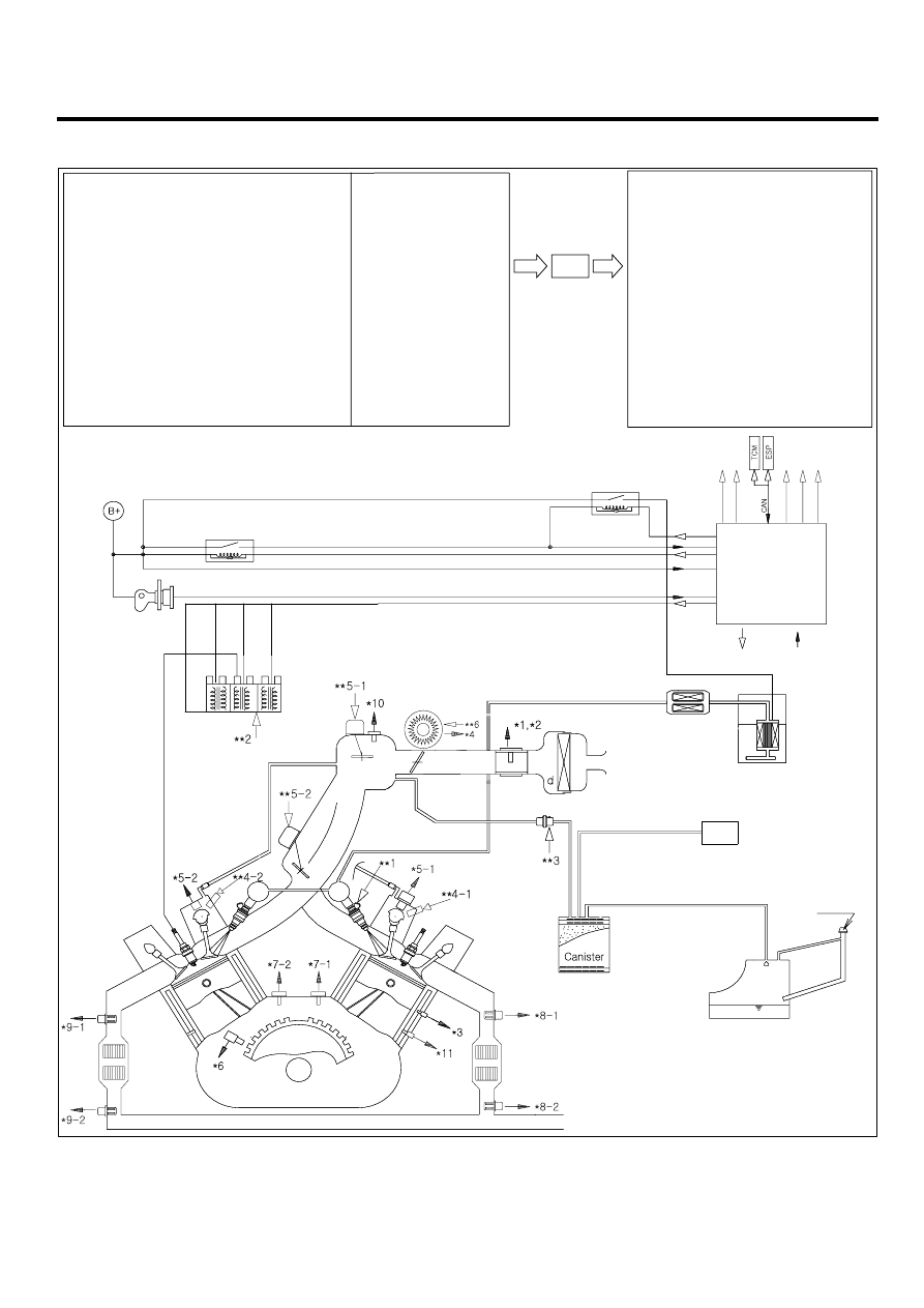
SCHEMATIC DIAGRAM
E6C3F98F
*1. Mass Air Flow Sensor (MAFS)
*2. Intake Air Temperature Sensor (IATS)
*3. Engine Coolant Tmeperature Sensor (ECTS)
*4. Throttle Position Sensor (TPS)
*5-1. Camshaft Position Sensor (CMPS) [BANK1]
*5-2. Camshaft Position Sensor (CMPS) [BANK2]
*6. Crankshaft Position Sensor (CKPS)
*7-1. Knock Sensor (KS) #1
*7-2. Knock Sensor (KS) #2
*8-1. Heated Oxygen Sensor (HO2S) [B1/S1]
*8-2. Heated Oxygen Sensor (HO2S) [B1/S2]
*9-1. Heated Oxygen Sensor (HO2S) [B2/S1]
*9-2. Heated Oxygen Sensor (HO2S) [B2/S2]
*10. Manifold Absolute Pressure Sensor (MAPS)
*11. CVVT Oil Temperature Sensor (OTS)
. Ignition Switch
. Battery Voltage
. Vehicle Speed Signal
. Coolant Load Signal
. "PNP" Switch (A/T only)
. Fuel Pump Relay Signal
PCM
**1. Fuel Injector
**2. Ignition Coil
**3. Purge Control Solenoid
Valve (PCSV)
**4-1. CVVT Oil control
valve (OCV) [BANK1]
**4-2. CVVT Oil control
valve (OCV) [BANK2]
**5-1. Variable Intake Manifold
Solenoid (VIS) Valve [Surge Tank]
**5-2. Variable Intake Manifold
Solenoid (VIS) Valve [Intake Manifold]
**6. ETC Motor
. Fuel Pump Control
. Main Relay
. Cooler Relay
. Ignition Timing Control
. Disagnosis
PCM
Fuel Filter
OUTPUT
INPUT
Fuel Pump
Fuel Tank
Air Cleaner
Fuel Tank
Air Filter
Fuel Tank
MCC
MCC
Spar
k Plug
Ignition
Switch
Main Relay
Battery
Fuel Pump Relay
LELG001K