Hyundai Santa Fe (2006 year). Manual - part 274
DS -56
DRIVESHAFT AND AXLE
REMOVAL
EC587D0E
1.
After making a match mark (C) on the rubber coupling
(A) and rear differential companion (B), remove the
propeller shaft mounting bolts (D).
Tightening torque Nm (kgf-m, lb-ft) :
49.0~68.6 (5~7, 36.2~50.6)
A
D
C
B
SCMDS6038D
2.
Remove the center bearing bracket (A) mounting bolts
(B).
Tightening torque Nm (kgf-m, lb-ft) :
39.2~49.0 (4~5, 28.9~36.2)
A
B
SCMDS6054D
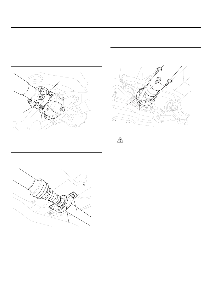
3.
After making a match mark (C) on the flange yoke (A)
and transaxle companion (B), remove the propeller
shaft mounting bolts (D).
Tightening torque Nm (kgf-m, lb-ft) :
49.0~68.6 (5~7, 36.2~50.6)
B
C
D
A
SCMDS6510D
CAUTION
Use the hexagonal wrench to prevent damage of
bolt head when removing bolts (D).
4.
Installation is the reverse of the removal procedures