Hyundai Santa Fe (2006 year). Manual - part 273


  Index      Hyundai     Hyundai Santa Fe - service repair manual 2006 year


Search            


Content   ..  271  272  273  274   ..


Hyundai Santa Fe (2006 year). Manual - part 273


DS -52

DRIVESHAFT AND AXLE

7.

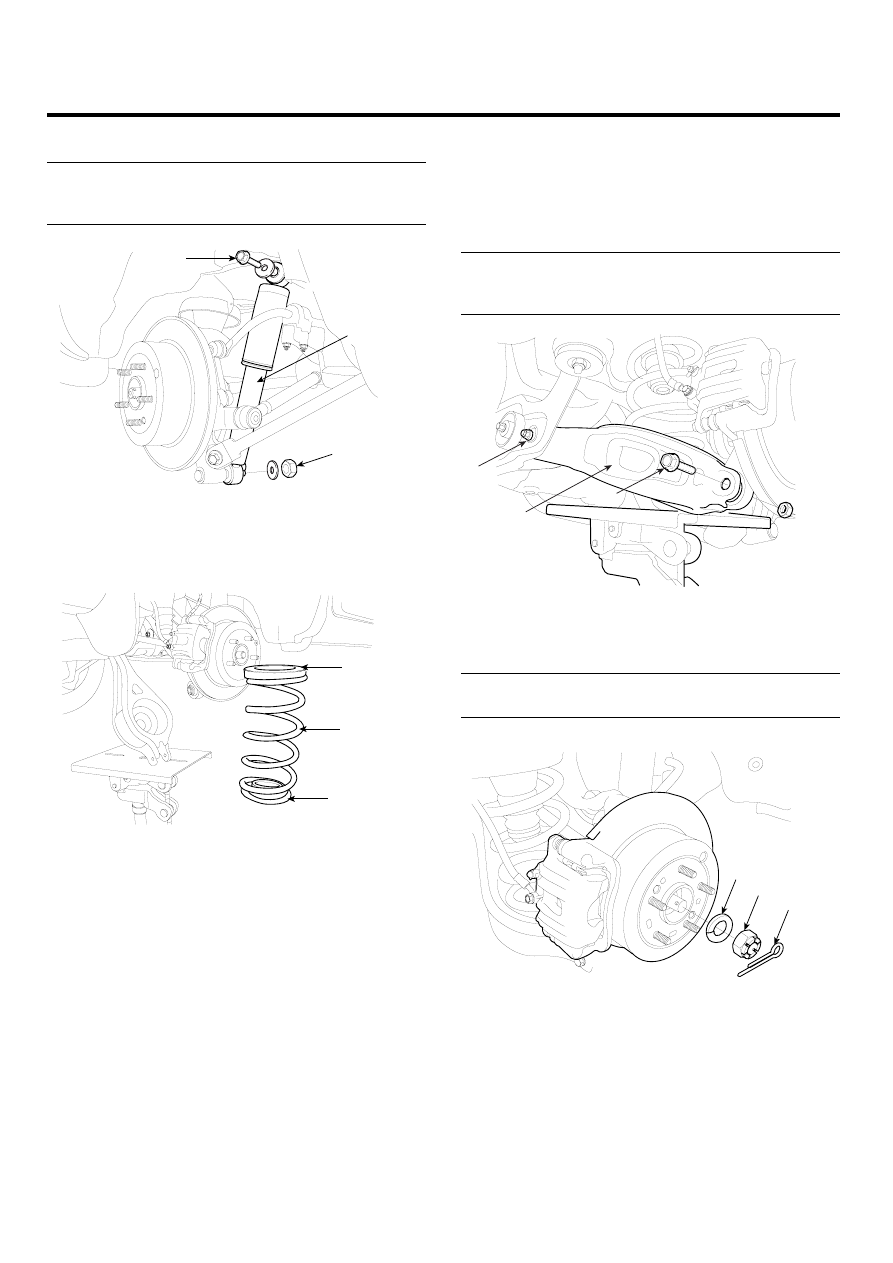
Install the rear shock absorber (A).

Tightening torque Nm (kgf-m, lb-ft) :
Bolt (B) : 137.3~156.9 (14~16, 101.3~115.7)
Nut (C) : 98.1~117.7 (10.0~12.0, 72.3~86.8)

A

C

B

SCMDS6023D

8.

Install the spring (A), the upper pad (B) and the lower
pad (C).

B

A

C

SCMDS6022D

9.

Install the mounting bolt (B) of the rear lower arm (A)
and the rear carrier with a specified torque, while sup-
porting the lower arm (A) with a jack as shown in
the illustration. Tighten the mounting bolt (C) of the
cross member and the rear lower arm with a speci-
fied torque.

Tightening torque Nm (kgf-m, lb-ft) :
Bolt (B) : 137.3~156.9 (14~16, 101.3~115.7)
Nut (C) : 137.3~156.9 (14~16, 101.3~115.7)

A

C

B

SCMDS6021D

10. Install the washer (C), castle nut (B) and split pin (A)

to the rear hub assembly.

Tightening torque Nm (kgf-m, lb-ft) :
196.1~255.0 (20~26, 144.7~188.1)

A

B

C

SCMDS6020D

REAR DRIVESHAFT ASSEMBLY

DS -53

CAUTION

The washer (B) should be assembled with convex
surface outward when installing the castle nut (A)
and split pin (C).

A

C

B

EIKD010A

11. Install the wheel and tire (A) to the rear hub (B).

Tightening torque Nm (kgf-m, lb-ft) :
88.3~107.9 (9~11, 65.1~79.6)

A

B

C

SCMDS6019D

CAUTION

Be careful not to damage the hub bolts (C) when
installing the rear wheel and tire (A).

DS -54

DRIVESHAFT AND AXLE

PROPELLER SHAFT
ASSEMBLY

PROPELLER SHAFT

COMPONENT

EAD08B0F

1. Front propeller shaft
2. Center bearing bracket
3. Rear propeller shaft

49.0 ~ 68.6

(5 ~ 7, 36.2 ~ 65.1)

49.0 ~ 68.6

(5 ~ 7, 36.2 ~ 65.1)

39.2 ~ 49.0 

(4.0 ~ 5.0, 28.9 ~ 36.2)

1

2

3

TORQUE : Nm (kgf.m, lb-ft)

SCMDS6516L

PROPELLER SHAFT ASSEMBLY

DS -55

INSPECTION

EDBA5EEC

CV JOINT AND BOOTS

1.

Shift the transaxle to Neutral.

2.

Raise the vehicle off the ground, and support it with
safety stands in the proper locations.

3.

Check the center bearing (A) for excessives play or
rattle and rubber for rent. If the center bearing (A) has
excessive play or rattle and rubber has rent, replace
the propeller shaft assembly.

A

B

C

SCMDS6036D

4.

Check the CV joint boot (B) for damage and deterio-
ration. If the boot is damaged or deteriored, replace
the propeller shaft assembly.

5.

Check the CV joint (C) for excessive play or rattle. If
the CV joint have excessive play or rattle, replace the
propeller shaft assembly.

PROPELLER SHAFT RUNOUT

1.

Install a dial indicator with its needle on the center of
front propeller shaft or rear propeller shaft.

2.

Turn the propeller shaft slowly and check the runout.
Repeat this procedure for the other propeller shaft.

Front Propeller Shaft Runout : 0.3mm (0.012in.)

SCMDS6037D

Rear Propeller Shaft Runout : 0.3mm (0.012in.)

SCMDS6055D

3.

If the runout on either propeller shaft exceeds the ser-
vice limit, replace the propeller shaft assembly.


Content   ..  271  272  273  274   ..