Hyundai Santa Fe (2006 year). Manual - part 271
DS -44
DRIVESHAFT AND AXLE
REAR DRIVESHAFT
ASSEMBLY
REAR DRIVESHAFT (DOJ-BJ
TYPE)
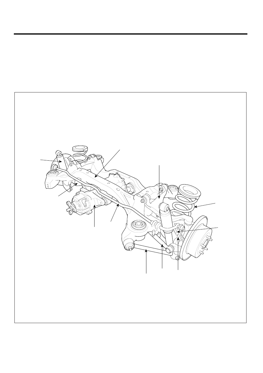
COMPONENT LOCATION
EDFAFE3C
1. Rear shock absorber assembly
2. Rear upper arm
3. Rear lower arm
4. Rear coil spring
5. Rear stabilizer bar assembly
6. Rear stabilizer link assembly
7. Rear cross member
8. Rear assist arm
9. Trailing arm
10. Differential Carrier (4WD)
11. Drive shaft (4WD)
7
1
3
10
5
9
8
6
11
4
2
SCMDS6514L