Hyundai Santa Fe (2006 year). Manual - part 258
CH -4
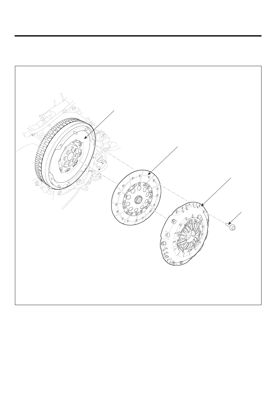
CLUTCH SYSTEM
CLUTCH COVER AND DISC
COMPONENTS
E501F1C7
TORQUE : Nm (kgf.m, lb-ft)
1. Engine flywheel
2. Clutch disc
3. Clutch cover
3
1
2
25~36(2.5~3.6,
18.2~26.2)
LOKG001B
|
|
|
CH -4 CLUTCH SYSTEM CLUTCH COVER AND DISC COMPONENTS E501F1C7 TORQUE : Nm (kgf.m, lb-ft) 1. Engine flywheel 3. Clutch cover 3 1 2 25~36(2.5~3.6, LOKG001B |