Hyundai Santa Fe (2006 year). Manual - part 246


  Index      Hyundai     Hyundai Santa Fe - service repair manual 2006 year


Search            


Content   ..  244  245  246  247   ..


Hyundai Santa Fe (2006 year). Manual - part 246


BR -156

BRAKE SYSTEM

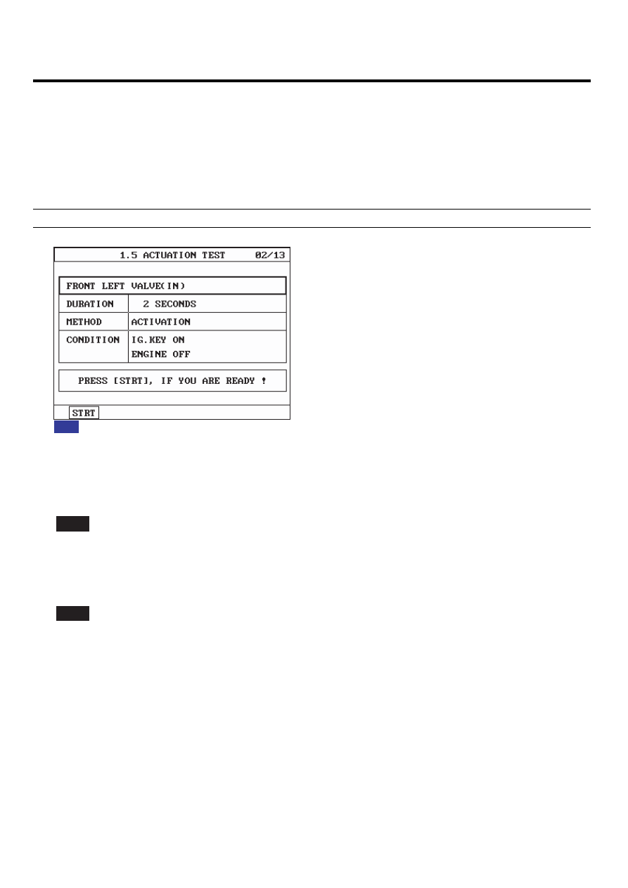
MONITOR ACTUATION TEST

EBFD31F0

1.

Connect scantool to Data Link Connector(DLC)

2.

Ignition "ON"

Engine "OFF".

3.

Select the "Actuation Test" mode on the scantool.

4.

Inspect opearating status of all vlaves with Actuation Test.

Specification : It’s normal if operating sound is heard.

Fig 1) Test Condition : Ignition "ON" & Engine "OFF". 
          Ex) Actuation Test on Front left valve(in)

Fig1

SCMBR6569L

5.

Do all valves operate normally?

YES

Fault is intermittent caused by poor connection in power harness (ABS2) and/or HECU’s connector or wasrepaired

and HECU memory was not cleared. Thoroughly check connectors for looseness, poor connection, bending, corro-
sion, contamination, deterioration, or damage. Repair or replace as necessary and then go to "Verification Of Vehicle
Repair" procedure.

NO

Go to "W/Harness Inspection" procedure.

TERMINAL

CONNECTOR INSPECTION

E91F6FE5

Refer to DTC C1200.

ABS (ANTI-LOCK BRAKE SYSTEM)

BR -157

POWER SUPPLY CIRCUIT INSPECTION

EB45563A

1.

Ignition "OFF".

2.

Disconnect HECU connector.

3.

Ignition "ON".

4.

Measure voltage between terminal "3" of the HECU harness connector and chassis ground.

Specification : Approx. B+

V

3. Battery(+)

1

5 6

8 9 10 11 12 13 14 15 16

18

20 21

26 27 28 29 30 31 32 33

35

37 38

2

3

4

*

*

*

* * * *

* * *

* *

*

*

*

*

*

<C281 GSL>

SCMBR6570L

5.

Is the measured voltage within specifications?

YES

Go to "Ground Circuit Inspection" procedure.

NO

Check for damaged harness and open or short to GND between the battery terminal(+) and terminal "3" of the

HECU harness connector. Check for open or blown 40A ABS fuse referring to "Circuit Diagram". Repair as necessary
and then go to "Verification of vehicle Repair" procedure.

GROUND CIRCUIT INSPECTION

E513968B

Refer to DTC C1101.

VERIFICATION OF VEHICLE REPAIR

E5E5A1F6

Refer to DTC C1101.

BR -158

BRAKE SYSTEM

DTC C2308 FL INLET VALVE MALFUNCTION
DTC C2316 FR INLET VALVE MALFUNCTION
DTC C2324 RL INLET VALVE MALFUNCTION
DTC C2332 RR INLET VALVE MALFUNCTION

COMPONENT LOCATION

E0DE60DF

Refer to DTC C1235.

GENERAL DESCRIPTION

EFB7DCDD

The HECU is composed of an ECU (Electronic Control Unit ) and an HCU( Hydraulic Control Unit), so the HECU hardware
includes all solenoid valves inside the unit as well as the ECU. Solenoid valves are switched to ON, OFF by HECU when
the ABS is activated. Solenoid valves function is to increase, decrease or maintain the hydralic pressure supplied to a
brake caliper.

DTC DESCRIPTION

ED337373

The HECU monitors the operation of the valves by checking the drive circuit of the solenid valves, and then sets this code
when the unexpcted drive voltage is detected. For example, the HECU sets the DTC if the electrical feedback signal does
not match the actuation signal for the corresponding valve.

ABS (ANTI-LOCK BRAKE SYSTEM)

BR -159

DTC DETECTING CONDITION

E9273E4B

Item

Detecting Condition

Possible cause

DTC Strategy

• Voltage monitoring

Monitoring

Period

• Continuous

Case 1

Enable

Conditions

• The electrical feedback signal does not match

the actuation signal for the corresponding
valve for more than 30 ms.
- Current controlled valves and under voltage
conditions :detection time is 80 ms

Monitoring

Period

• Immediately after power on
• every 20 s

- The Test is canceled if any control, valve
actuation takes place or if the Vehicle is in
motion and the BLS is on.

Case 2

Enable

Conditions

• A Fault is found if UVR is not within 0.1*battery

voltage

valve relay voltage

0.8*battery voltage

• A Fault is found if valve relay voltage

0.2*battery voltage.
- After that all valves are switched on sequential,
valve relay voltage and valve feedback is measured.

Monitoring

Period

• The Valve and Pump motor Test is performed once

after ignition on if vehicle speed is

= 15 km/h.

Case 3

Enable

Conditions

• The valve and pump motor test detects electrical

actuation malfunction of ABS valves. The test
actuates all valves in series (to detect short cuts
or shunts between the valve lines). Faults are
detected if there is an error during the test.

Monitoring

Period

• The drift test executes only once during an ignition

Cycle. The test is triggered if the following conditions
are fulfilled : 10min after power up or end of control
1)

No BLS is applied

2)

Brake pressure is

10 bar

3)

Vehicle speed

15 km/h

4)

Vehicle acceleration

0.5 m/s

²

5)

Supply voltage

11 volts.

Case 4

Enable

Conditions

• The drift test is executed only once during an

ignition Cycle.If it detects partly shorted valve
coils,almost inoperative coils or malfunction of
the valve driver, a failure is recognized.

Fail Safe

• Valve cannot be actuated or valve is incorrectly

actuated. This may result in locked wheels
or wheels without pressure.

• ABS/EBD/ESP function is prohibited.
• ABS/EBD/ESP warning lamp is turned ON.

• Inoperative HECU


Content   ..  244  245  246  247   ..