Hyundai Santa Fe (2006 year). Manual - part 217
BR -40
BRAKE SYSTEM
PARKING BRAKE CABLE ADJUSTMENT
CAUTION
Parking brake cable adjustment must be carried
out after adjusting rear shoe.
HAND TYPE
1.
Operate the parking brake lever through a full stoke
over 3 times for setting the cables.
2.
The travel must be between 6 ~ 7 notches when apply-
ing a force of approx. 20kgf (196N, 44.1lb) at 40mm
(1.57in) from the end of lever assembly by adjusting
nut (A) of equalizer.
A
SCMBR6516L
3.
The parking brake indicator lamp must be OFF when
lever assembly is released, and ON when operating
by 1 notch.
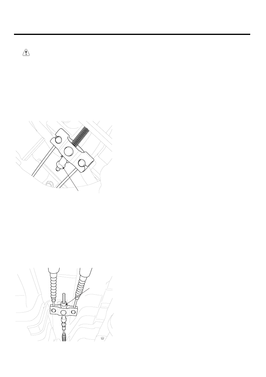
FOOT TYPE
4.
Operate the parking brake pedal through a full stroke
over 3 times for setting the cables.
5.
Adjust the adjusting nut (A) for parking brake pedal
stroke 130 ~ 140mm when operating effort is approx.
30kgf (294N, 66lb).
A
SCMBR6517L