Hyundai Santa Fe (2006 year). Manual - part 164
INDICATORS AND GAUGES
BE -117
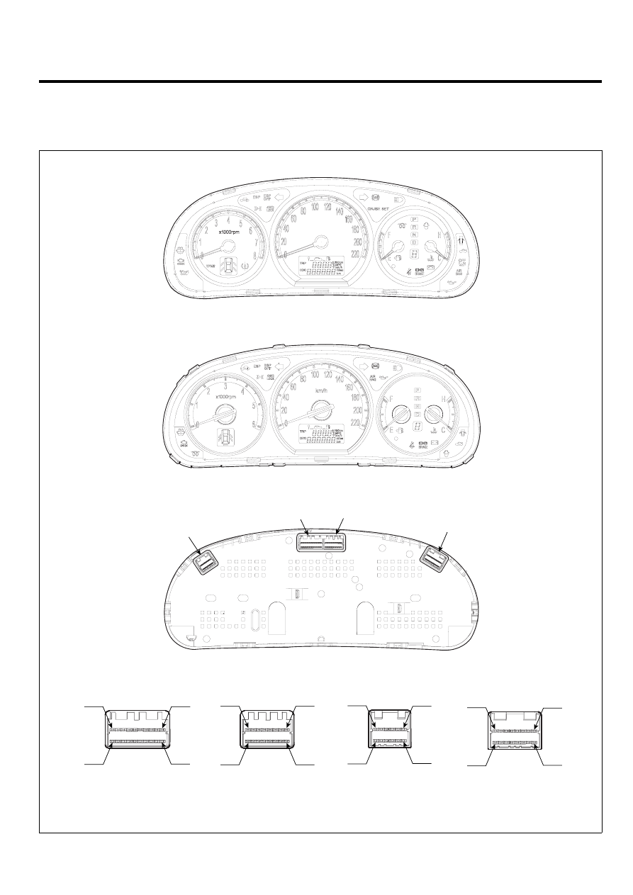
INSTRUMENT CLUSTER
COMPONENTS
E5E2EEB4
Connector C
Connector A
Connector A
Connector B
Connector C
Connector D
Connector B
Connector D
km/h
<STANDARD>
<SUPER VISION>
8
16
1
9
1
10
11
20
1
6
7
12
1
8
9
16
SCMBE6221L