Hyundai Santa Fe (2006 year). Manual - part 149
KEYLESS ENTRY AND BURGLAR ALARM
BE -57
INSPECTION
EAD8ECED
FRONT DOOR LOCK ACTUATOR
1.
Remove the front door trim.
(Refer to the Body group - Front door)
2.
Remove the front door module.
(Refer to the Body group - Front door).
3.
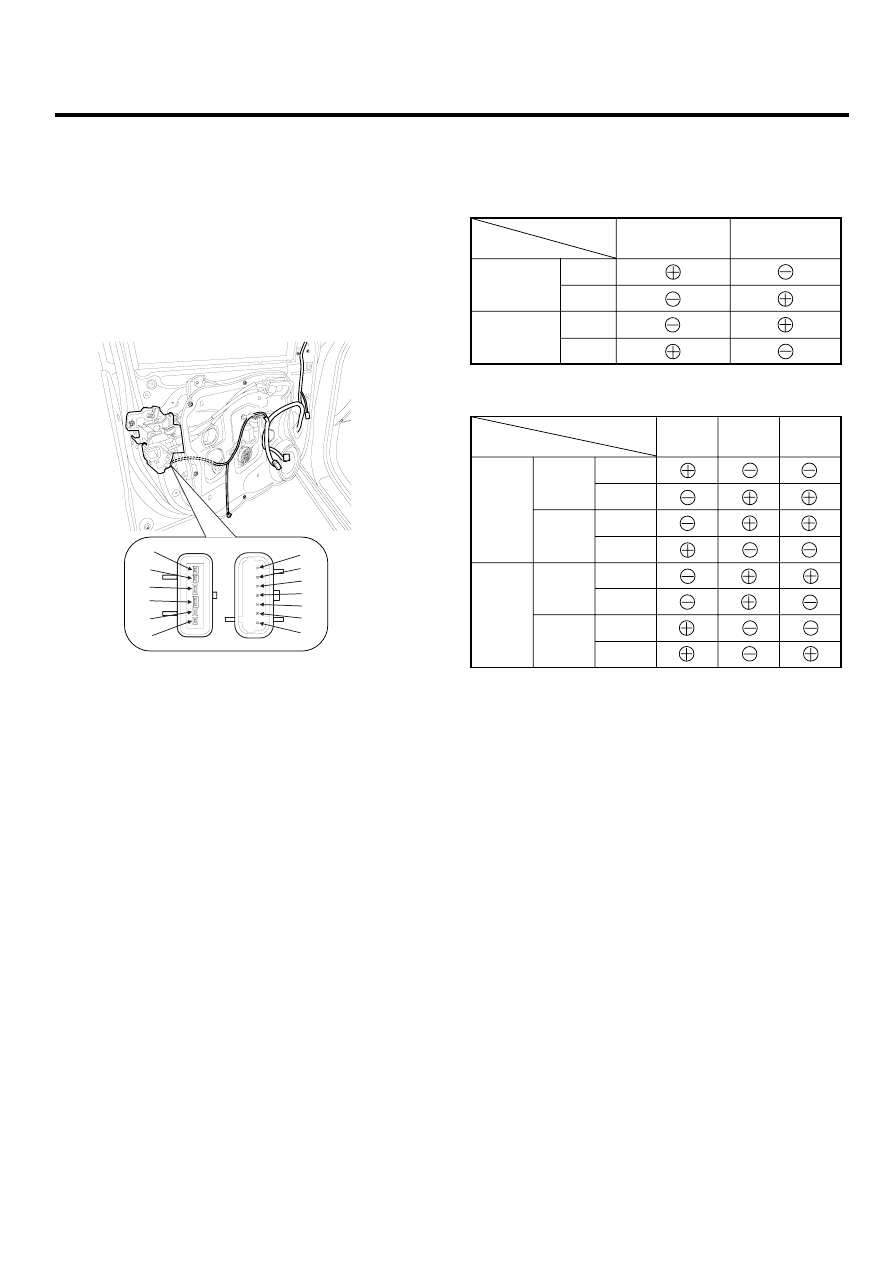
Disconnect the connectors from the actuator.
1
2
3
4
5
6
7
1
2
3
4
5
6
[CENTRAL LOCK]
[DEAD LOCK]
SCMBE6130L
4.
Check actuator operation by connecting power and
ground according to the table. To prevent damage to
the actuator, apply battery voltage only momentarily.
Terminal
Position
Front left
Unlock
Lock
Unlock
Lock
Front right
4
3
[CENTRAL LOCK]
SCMBE6131L
Terminal
Position
Front
left
Central
Lock
Dead
Lock
Unlock
Lock
Unlock
Lock
Unlock
Lock
Unlock
Lock
Front
right
Front
left
Front
right
5
6
7
[DEAD LOCK]
SCMBE6144L