Hyundai Santa Fe (2006 year). Manual - part 142
AUDIO SYSTEM
BE -29
ANTENNA
INSPECTION
E14AC1A5
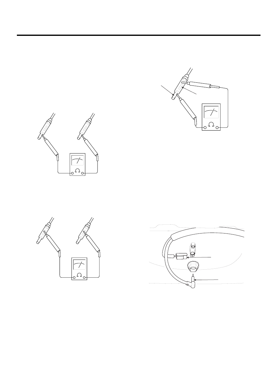
ANTENNA CABLE
1.
Remove the antenna jack from the audio unit and an-
tenna.
2.
Check for continuity between the center poles of an-
tenna cable.
ATJF023C
3.
Check for continuity between the outer poles of an-
tenna cable. There should be continuity.
ATJF023D
4.
If there is no continuity, replace the antenna cable.
5.
Check for continuity between the center pole of an-
tenna cable and terminal of glass antenna. There
should be continuity.
A
B
ATJF023F
6.
If there is continuity, replace the antenna cable.
REPLACEMENT
E8FE7EEC
1.
Remove the rear roof trim.
(Refer to the Body group - Roof trim).
2.
Disconnect the 1P power connector (A) and antenna
jack (B) from the roof antenna.
3.
Remove the roof antenna after removing a nut.
A
B
SCMBE6031D
4.
Installation is the reverse of removal.