Hyundai Santa Fe (2006 year). Manual - part 136
GENERAL
BE -5
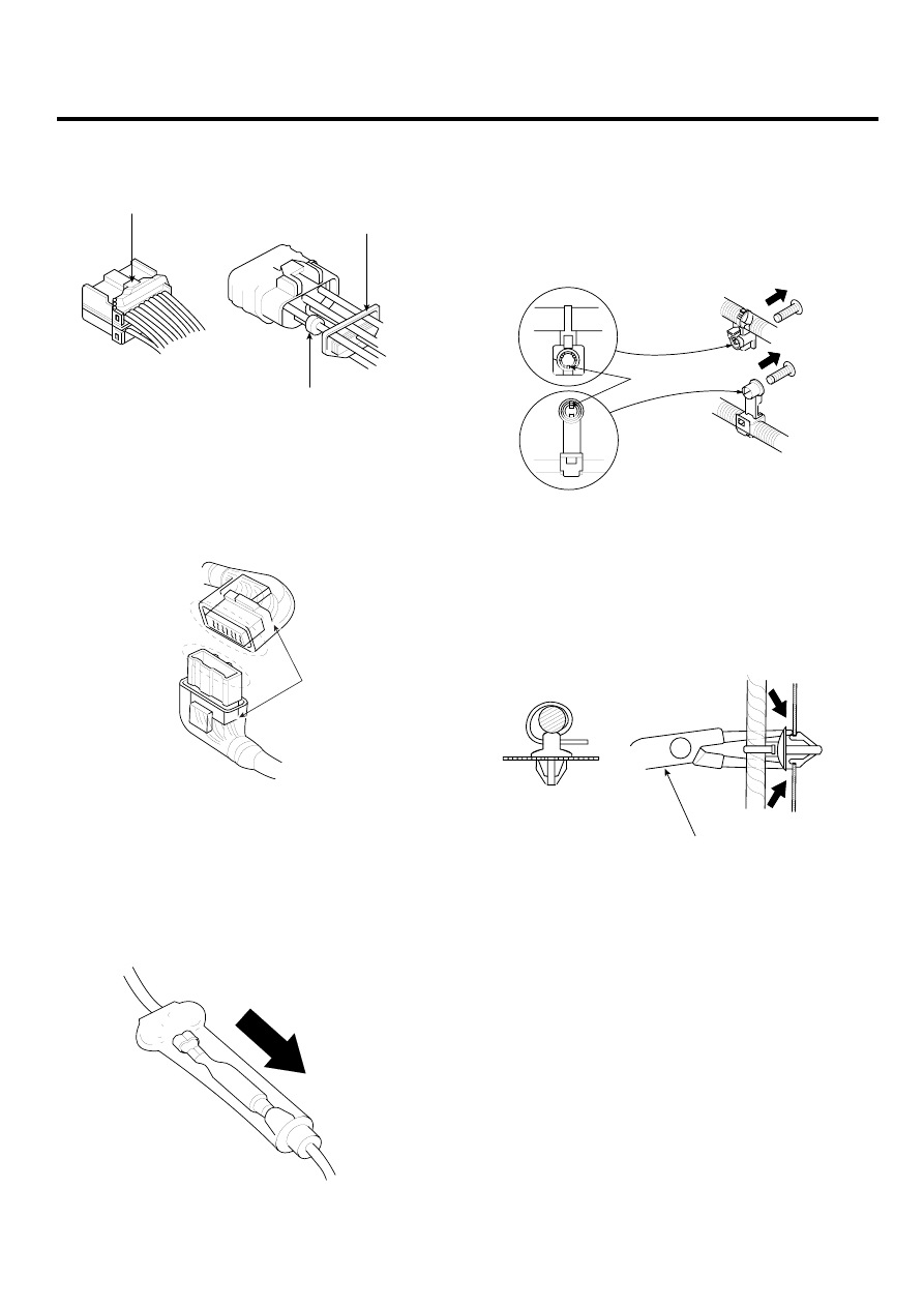
9.
Check for loose retainer (A) and rubber seals (B).
A
A
B
ETKD150E
10. The backs of some connectors are packed with
grease. Add grease if necessary. If the grease (A) is
contaminated, replace it.
A
ETKD150F
11. Insert the connector all the way and make sure it is
securely locked.
12. Position wires so that the open end of the cover faces
down.
DOWN
ETKD150G
HANDLING WIRES AND HARNESSES
1.
Secure wires and wire harnesses to the frame with
their respective wire ties at the designated locations.
2.
Remove clips carefully; don’t damage their locks (A).
A
ETKD150H
3.
Slip pliers (A) under the clip base and through the hole
at an angle, and then squeeze the expansion tabs to
release the clip.
A
ETKD150I
4.
After installing harness clips, make sure the harness
doesn’t interfere with any moving parts.
5.
Keep wire harnesses away from exhaust pipes and
other hot parts, from sharp edges of brackets and
holes, and from exposed screws and bolts.