Hyundai Santa Fe (2006 year). Manual - part 97


  Index      Hyundai     Hyundai Santa Fe - service repair manual 2006 year


Search            


Content   ..  95  96  97  98   ..


Hyundai Santa Fe (2006 year). Manual - part 97


ATA -146

AUTOMATIC TRANSAXLE (A5HF1)

SIGNAL WAVEFORM

E59EC1CB

LKKG115A

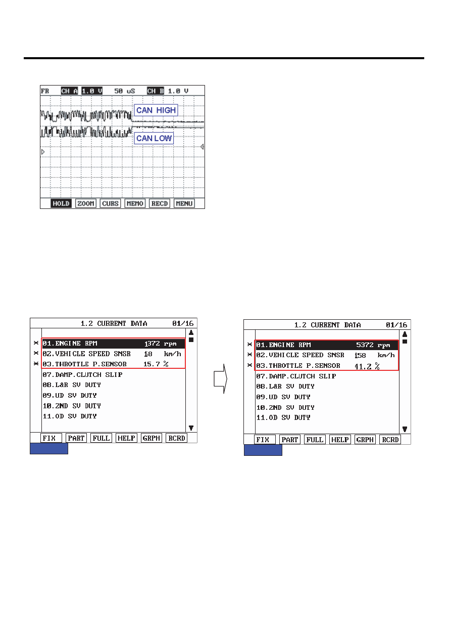
MONITOR SCANTOOL DATA

ED1236B5

1.

Connect scantool to data link connector(DLC).

2.

Engine "ON".

3.

Monitor the "CAN COMMUNICATION SERVICE DATA (ENGINE RPM, VEHICLE SPEED SENSOR, THROTTLE P.
SENSOR)" parameters on the scantool.

FIG.1) Low-RPM

FIG.2) High-RPM

FIG.1)

FIG.2)

LKKG115B

AUTOMATIC TRANSAXLE SYSTEM

ATA -147

4.

Does "CAN BUS LINE DATA " follow the reference data?

YES

▶ Fault is intermittent caused by poor contact in the sensor’s and/or TCM(PCM)’s connector or was repaired and
TCM(PCM) memory was not cleared. Thoroughly check connectors for looseness, poor connection, bending, cor-
rosion, contamination, deterioration or damage. Repair or replace as necessary and go to "Verification of Vehicle
Repair" procedure .

NO

▶ Go to "Terminal&Connector Inspection" procedure.

TERMINAL & CONNECTOR INSPECTION

EF5197C6

1.

Many malfunctions in the electrical system are caused by poor harness and terminals. Faults can also be caused by
interference from other electrical systems, and mechanical or chemical damage.

2.

Thoroughly check connectors for looseness, poor connection, bending, corrosion, contamination, deterioration, or
damage.

3.

Has a problem been found?

YES

▶ Repair as necessary and then go to "Verification of Vehicle Repair" procedure .

NO

▶ Go to "Signal circuit inspection" procedure .

SIGNAL CIRCUIT INSPECTION

E123A3DB

1.

Ignition "ON" & Engine "OFF".

2.

Disconnect the "TCM" and "ABS ECM" connector.

3.

Measure Resistence between terminal 3 and 4 of the TCM harness connector.

Specification : Approx. 120 ± 10 Ω

ATA -148

AUTOMATIC TRANSAXLE (A5HF1)

C224-C

22

21

-

-

18 17 16

-

-

13

12

1

3

4

5

6

7

8

9

-

-

-

SCMAT6411L

4.

Is measured resistance within specifications?

YES

▶ Substitute with a known-good PCM/TCM and check for proper operation. If the problem is corrected, replace
PCM/TCM as necessary and then go to "Verification of Vehicle Repair" procedure.

NO

▶ Check connectors for looseness, poor connection, bending, corrosion, contamination, deterioration or damage of
ECM.and then Repair or replace Resistance for CAN communication as necessary and go to "Verification of Vehicle
Repair" procedure .

VERIFICATION OF VEHICLE REPAIR

E9FE64EC

After a repair, it is essential to verify that the fault has been corrected.

1.

Connect scan tool and select "Diagnostic Trouble Codes(DTCs)" mode.

2.

Using a scantool, Clear DTC.

3.

Operate the vehicle within DTC Enable conditions in General information.

4.

Are any DTCs present?

YES

▶ Go to the applicable troubleshooting procedure.

NO

▶ System performing to specification at this time.

AUTOMATIC TRANSAXLE SYSTEM

ATA -149

DTC U0100 CAN MI-COM OR CIRCUIT MAL.

COMPONENT LOCATION

ECCDDB76

Refer to DTC U0001.

GENERAL DESCRIPTION

EC72F81B

Refer to DTC U0001.

DTC DESCRIPTION

E328681E

Refer to DTC U0001.

DTC DETECTING CONDITION

EDCB1F3F

Item

Detecting Condition

Possible cause

DTC Strategy

• Check voltage range

Enable Conditions

• Not Fail Safe Status
• IG "ON"
• Ne ≥ 100rpm

Threshold value

• Receive a message "BUS OFF" from CAN MI-COM

Diagnostic Time

• More than 1.5 sec

Fail Safe

• INTELLIGENT SHIFT and is inhibited
• learning for oil pressure control is inhibited
• Torque Retard requirement is inhibited
• direct connection control of TCC is inhibited

• Open or Short in CAN

communication harness

• Faulty ECM
• Faulty TCM

SIGNAL WAVEFORM

E59B3434

Refer to DTC U0001.


Content   ..  95  96  97  98   ..