Hyundai Santa Fe (2006 year). Manual - part 96


  Index      Hyundai     Hyundai Santa Fe - service repair manual 2006 year


Search            


Content   ..  94  95  96  97   ..


Hyundai Santa Fe (2006 year). Manual - part 96


ATA -142

AUTOMATIC TRANSAXLE (A5HF1)

1

2

4

3

1

2

3

-

-

-

-

-

-

-

-

-

-

-

11

12

13

26

25

24

22 21

19

16

15

14

C224-A

1.Battery
2.Ground

4.A/T control relay

C236

SCMAT6403D

3)

Is resistance within specifications?

YES

▶ Go to "Ground circuit inspection" procedure.

NO

▶ Check that A/T-20A Fuse in engine room junction is installed or not blown.
▶ Check for open in harness. Repair as necessary and Go to "Verification of Vehicle Repair" procedure.

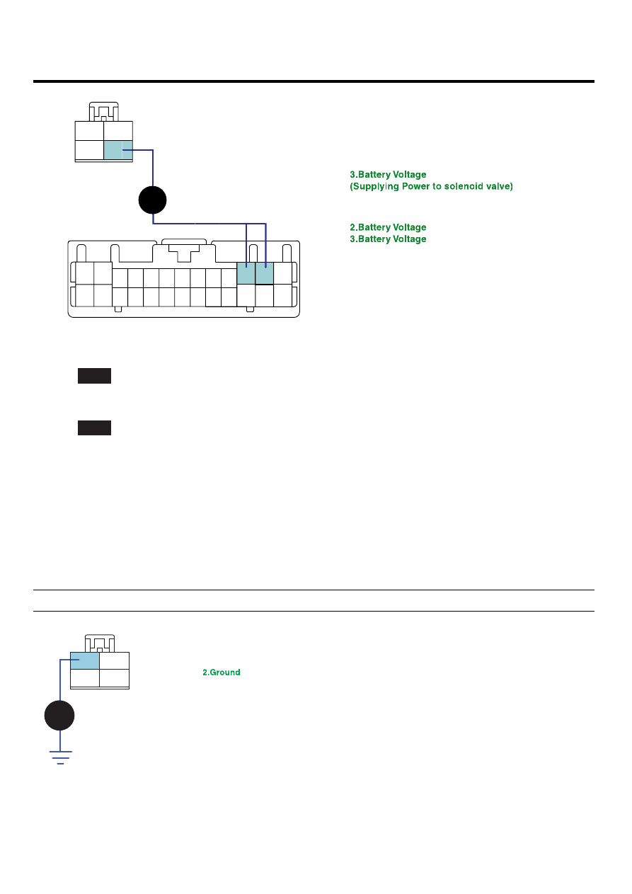
GROUND CIRCUIT INSPECTION

E8CC970F

1.

Ignition "OFF".

2.

Connect the "A/T CONTROL RELAY" connector.

3.

Measure the resistance between terminal "2" of the "A/T CONTROL RELAY" harness connector and chassis ground.

Specification : Approx. 0 Ω

1.Battery

3.Battery Voltage
(Supplying Power to solenoid valve)
4.A/T control relay

C236

1

2

4

3

SCMAT6404D

AUTOMATIC TRANSAXLE SYSTEM

ATA -143

4.

Is resistance within specifications?

YES

▶ Go to "Component inspection" procedure.

NO

▶ Check for open in harness. Repair as necessary and Go to "Verification of Vehicle Repair" procedure.

COMPONENT INSPECTION

E49EFEFE

1.

Ignition "OFF".

2.

Remove "A/T CONTROL RELAY".

3.

Measure the resistance between each terminal of the sensor.

Specification:

Item

Terminal No

1(red) - 3(black)

INFINITE

Resistance

2(black) - 4(red)

supply(B+) to number 4 and supply (B-) to number 2

1(red) - 3(black)

C236

2

1

3

4

SCMAT6405D

4.

Is resistance with in specifications?

YES

▶ Thoroughly check connectors for looseness, poor connection, bending, corrosion, contamination, deterioration, or
damage. Repair or replace as necessary and then go to "Verification of Vehicle Repair" procedure.

NO

▶ Replace ATM CONTROL RELAY and then go to "Verification of Vehicle Repair" procedure.

ATA -144

AUTOMATIC TRANSAXLE (A5HF1)

VERIFICATION OF VEHICLE REPAIR

ED2CF808

After a repair, it is essential to verify that the fault has been corrected.

1.

Connect scantool and select "Diagnostic Trouble Codes(DTCs)" mode.

2.

Using a scantool, Clear DTC.

3.

Operate the vehicle within DTC Enable conditions in General information.

4.

Are any DTCs present ?

YES

▶ Go to the applicable troubleshooting procedure.

NO

▶ System performing to specification at this time.

AUTOMATIC TRANSAXLE SYSTEM

ATA -145

DTC U0001 CAN COMMUNICATION MALFUNCTION

COMPONENT LOCATION

EA761FDF

SCMAT6306D

GENERAL DESCRIPTION

EBB0AD30

The TCM can either receive data from the Engine Control Module or ABS control module, or it can send data to the ECM
and ABSCM by using CAN communication. The CAN communicaton is one of the vehicle communications method, which
is now widely used to transfer the vehicle data.

DTC DESCRIPTION

E03977FB

When the TCM cannot read the data from the ECM through the CAN-BUS line, the TCM sets this code.
CAN-BUS circuit malfunctioning or ECM can be a posssible cause of this DTC.

DTC DETECTING CONDITION

EDF2BE4D

Item

Detecting Condition

Possible cause

DTC Strategy

• Check voltage range

Enable Conditions

• Not Fail Safe Status
• IG "ON"
• Ne ≥ 100rpm

Threshold value

• Receive a message "BUS OFF" from CAN MI-COM

Diagnostic Time

Fail Safe

• INTELLIGENT SHIFT and is inhibited
• Learning for oil pressure control is inhibited
• Torque Retard requirement is inhibited
• Direct connection control of TCC is inhibited

• Open or Short in CAN

communication harness

• Faulty ECM
• Faulty TCM


Content   ..  94  95  96  97   ..