Hyundai Santa Fe (2006 year). Manual - part 87
ATA -106
AUTOMATIC TRANSAXLE (A5HF1)
5.
Does "LR SOLENOID DUTY " follow the reference data?
YES
▶ Fault is intermittent caused by poor contact in the sensor’s and/or TCM(PCM)’s connector or was repaired and
TCM(PCM) memory was not cleared. Thoroughly check connectors for looseness, poor connection, bending, cor-
rosion, contamination, deterioration or damage. Repair or replace as necessary and go to "Verification of vehicle
repair" procedure.
NO
▶ Go to "Terminal&connector inspection " procedure.
TERMINAL & CONNECTOR INSPECTION
E8E9D1C6
Refer to DTC P0743.
POWER SUPPLY CIRCUIT INSPECTION
EEDFC93C
1.
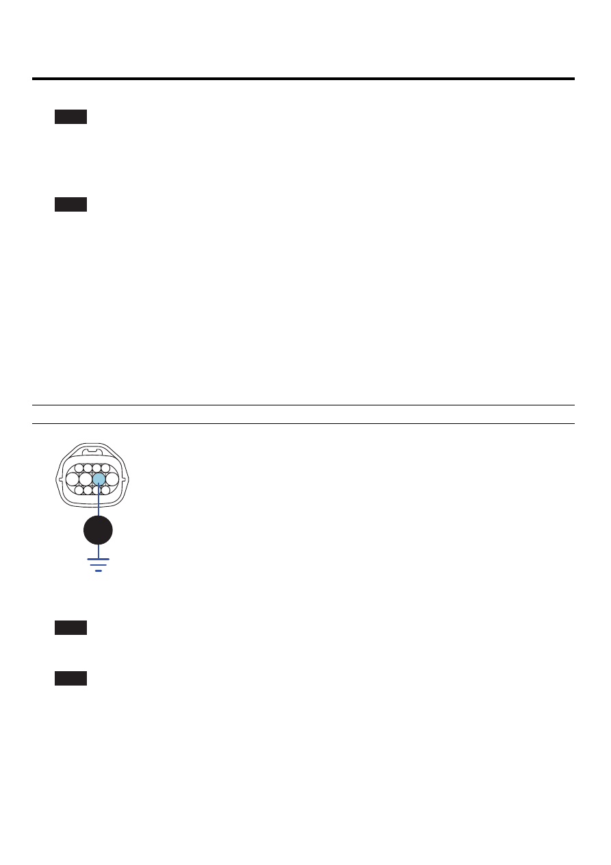
Disconnect "A/T SOLENOID VALVE" connector.
2.
Measure voltage between terminal "6" of the sensor harness connector and chassis ground.
3.
Engine OFF → ON.
Specification: 12V is measured only for approx. 0.5sec
1
2
3
4
5
6
7
8
9
10
11
12
3. UD solenoid valve
4. 2ND solenoid valve
5. A/T battery
6. A/T battery
7. VF solenoid valve(-)
8. VF solenoid valve(+)
9. DCC solenoid valve
10.RED solenoid valve
11. LR solenoid valve
12. OD solenoide valve
C209
v
SCMAT6361L
4.
Is voltage within specifications?
YES
▶ Go to "Signal circuit inspection" procedure.
NO
▶ Check that A/T-20A fuse in engine room junction is installed or not blown.
▶ Check for open in harness. Repair as necessary and go to "Verification of vehicle repair" procedure.