Hyundai Santa Fe (2006 year). Manual - part 74
ATA -54
AUTOMATIC TRANSAXLE (A5HF1)
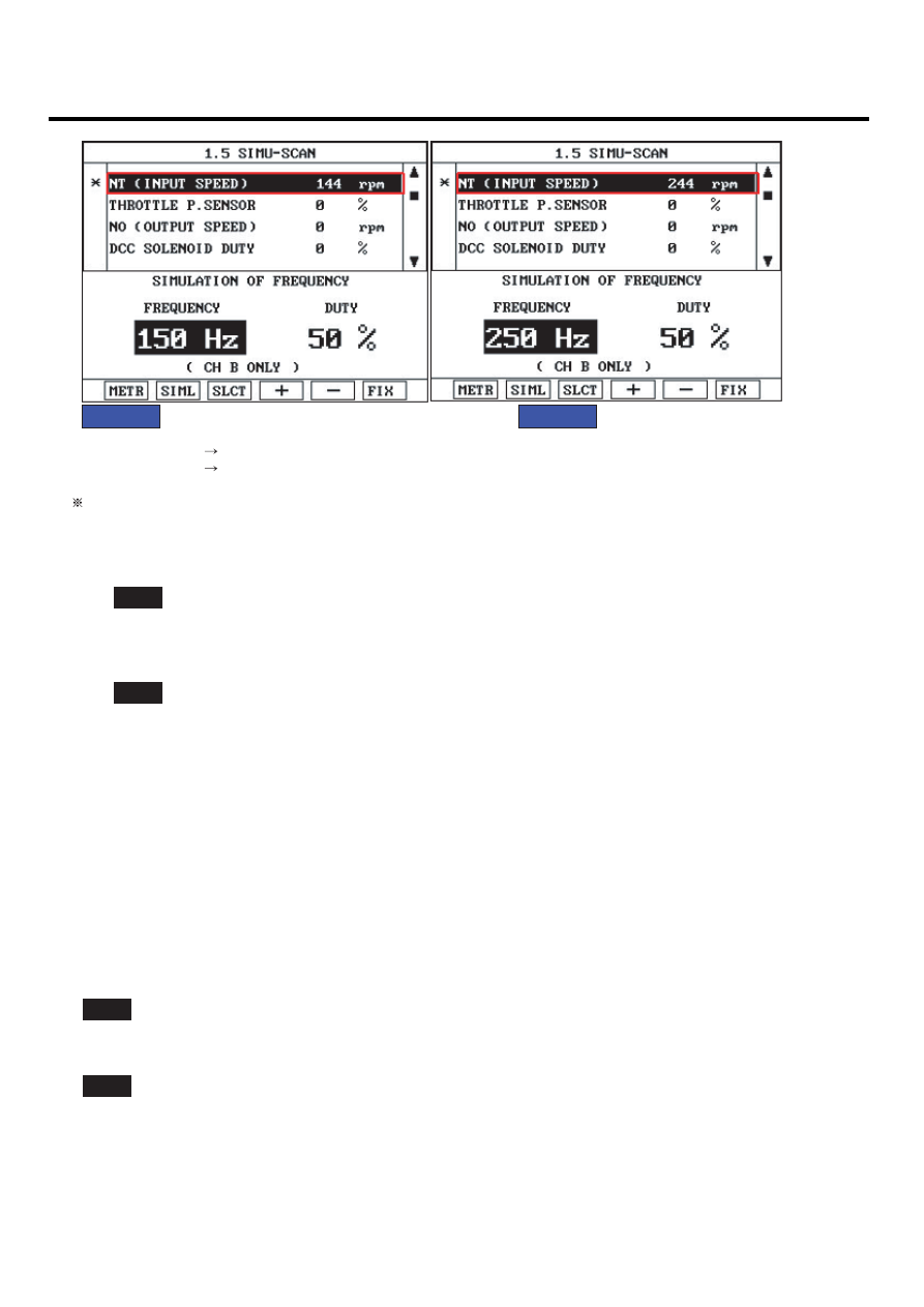
FIG.1)
FIG.2)
FIG.1) INPUT 150Hz
144rpm
FIG.2) INPUT 250Hz
244rpm
The values are subject to change according to vehicle model or conditions
EKBF105G
5)
Is "INPUT SPEED SENSOR" signal value changed according to simulation frequency?
YES
▶ Thoroughly check connectors for looseness, poor connection, bending, corrosion, contamination, deteriora-
tion, or damage. Repair or replace as necessary and then go to "Verification of Vehicle Repair" procedure.
NO
▶ Substitute with a known-good PCM/TCM and check for proper operation. If the problem is corrected, replace
PCM/TCM as necessary and then go to "Verification of Vehicle Repair" procedure.
VERIFICATION OF VEHICLE REPAIR
EE5DDD84
After a repair, it is essential to verify that the fault has been corrected.
1.
Connect scan tool and select "Diagnostic Trouble Codes(DTCs)" mode.
2.
Using a scan tool, Clear DTC.
3.
Operate the vehicle within DTC Enable conditions in General information.
4.
Is resistance within specification ?
YES
▶ Go to the applicable troubleshooting procedure.
NO
▶ System performing to specification at this time.