Hyundai Santa Fe (2006 year). Manual - part 31


  Index      Hyundai     Hyundai Santa Fe - service repair manual 2006 year


Search            


Content   ..  29  30  31  32   ..


Hyundai Santa Fe (2006 year). Manual - part 31


AT -76

AUTOMATIC TRANSAXLE (F4A51)

DTC P0722 OUTPUT SPEED SENSOR CIRCUIT - NO SIGNAL
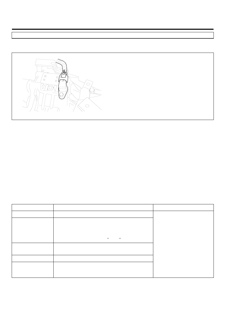
COMPONENT LOCATION

E262AC7C

BKQE005A

GENERAL DESCRIPTION

E8B3A5DF

The Output Speed Sensor outputs pulse-signals according to the revolutions of the output shaft of the transmission. The
Output Speed Sensor is installed in front of the Transfer Drive Gear to determine the Transfer Drive Gear rpms by counting
the frequency of the pulses. This value, together with the throttle position data, is mainly used to decide the optimum gear
position.

DTC DESCRIPTION

EADEF85D

The TCM sets this code if the calculated value of the pulse-signal is noticeably different from the value calculated, using
the Vehicle Speed Sensor output, when the vehicle is running faster than 30 km/h. The TCM will initiate the fail safe
function if this code is detected.

DTC DETECTING CONDITION

E8B5DC1C

Item

Detecting Condition

Possible cause

DTC Strategy

• Speed rationality check

Enable Conditions

• Vehicle speed is over 19 Mile/h(30 Km/h) and

Ne≥ 1000rpm in D,3,2,L(A/T range switch)
and SP(SPORTS MODE)

• 11V ≤ Battery Voltage ≤ 16V
• TM oil temperature ≥ -23 C(-9.4 F)

Threshold value

• Vehicle speed calculated from output speed ≤

10%(the vehicle speed from vehicle speed sensor)

Diagnostic Time

• More than 1sec

Fail Safe

• Locked into 3rd or 2nd gear.
• Apply an electric current to solenoid valve
• Manual shifting is possible(2 nd → 3 rd, 3 rd → 2 nd)

• Signal circuit is open or short
• Sensor power circuit is open
• Sensor ground circuit is open
• Faulty OUTPUT SPEED

SENSOR

• Faulty PCM

AUTOMATIC TRANSAXLE SYSTEM

AT -77

SPECIFICATION

E5381A0E

Input shaft & Output shaft speed sensor

• Type : Hall sensor
• Current consumption : 22mA(MAX)
• Sensor body and sensor connector have been unified as one.

SIGNAL WAVEFORM

EB18EDEE

LLLG106B

MONITOR SCANTOOL DATA

E4C2F196

1.

Connect scantool to data link connector(DLC).

2.

Engine "ON".

3.

Monitor the "OUTPUT SPEED SENSOR" parameter on the scantool.

4.

Driving at speed of over 19 Mile/h(30 Km/h).

Specification : Increasing Gradually

FIG.1)

FIG.2)

FIG.1) Low-speed
FIG.2) High-speed

SCMAT6720L

AT -78

AUTOMATIC TRANSAXLE (F4A51)

5.

Does "Output speed sensor" follow the reference data?

YES

▶ Fault is intermittent caused by poor contact in the sensor’s and/or TCM(PCM)’s connector or was repaired and
TCM(PCM) memory was not cleared. Thoroughly check connectors for looseness, poor connection, bending, cor-
rosion, contamination, deterioration or damage. Repair or replace as necessary and go to "Verification of Vehicle
Repair" procedure.

NO

▶ Go to "Terminal & connector inspection" procedure.

TERMINAL & CONNECTOR INSPECTION

E1DDBA29

1.

Many malfunctions in the electrical system may be caused from poor harness and terminals. These faults can be
caused by interference from other electrical systems and mechanical or chemical damage.

2.

Thoroughly check connectors for looseness, poor connection, bending, corrosion, contamination, deterioration, or
damage.

3.

Has a problem been found?

YES

▶ Repair as necessary and go to "Verification of vehicle Repair" procedure.

NO

▶ Go to "Signal circuit inspection" procedure.

SIGNAL CIRCUIT INSPECTION

E3695DC8

1.

Ignition "ON" & Engine "OFF".

2.

Disconnect the "OUTPUT SPEED SENSOR" connector.

3.

Measure voltage between terminal "2" of the OUTPUT SPEED SENSOR harness connector and chassis ground.

Specification : approx. 5V

C43

1. Sensor ground 

2. Output speed sensor

3. Power supply IG1

1

2

3

SCMAT6721L

AUTOMATIC TRANSAXLE SYSTEM

AT -79

4.

Is voltage within specification?

YES

▶ Go to "Power circuit Inspection" procedure.

NO

▶ Check for open or short in harness. Repair as necessary and Go to "Verification of Vehicle Repair" procedure.
▶ If signal circuit in harness is OK, Go to "Check PCM/TCM" of the "Component Inspection" procedure.

POWER SUPPLY CIRCUIT INSPECTION

EFBB0B79

1.

Ignition "ON" & Engine "OFF".

2.

Disconnect the "OUTPUT SPEED SENSOR" connector.

3.

Measure voltage between terminal "3" of the "OUTPUT SPEED SENSOR" harness connector and chassis ground.

Specification : approx. B+

C43

1. Sensor ground 
2. Output speed sensor

3. Power supply IG1

1

2

3

SCMAT6722L

4.

Is voltage within specification?

YES

▶ Go to "Ground circuit inspection" procedure.

NO

▶ Check for open in harness. Repair as necessary and Go to "Verification of Vehicle Repair" procedure.


Content   ..  29  30  31  32   ..