Hyundai Santa Fe (2006 year). Manual - part 24


  Index      Hyundai     Hyundai Santa Fe - service repair manual 2006 year


Search            


Content   ..  22  23  24  25   ..


Hyundai Santa Fe (2006 year). Manual - part 24


AT -48

AUTOMATIC TRANSAXLE (F4A51)

DTC P0707 TRANSAXLE RANGE SWITCH - LOW INPUT
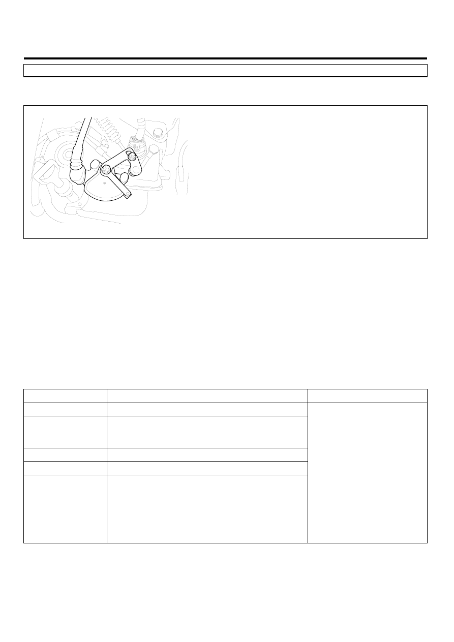
COMPONENT LOCATION

E9A1E3F5

EKKE108A

GENERAL DESCRIPTION

E2CDEB72

The Transaxle Range Switch sends the shift lever position information to the TCM(PCM) using a 12V (battery voltage)
signal. When the shift lever is in the D (Drive) position the output signal of Transaxle Range Switch is 12V and in all other
positions the voltage is 0V. The TCM(PCM) judges the shift lever position by reading all signals, for the Transaxle Range
Switch, simultaneously.

DTC DESCRIPTION

EA59FEC0

The TCM(PCM) sets this code when the Transaxle Range Switch has no output signal for more than 30 seconds.

DTC DETECTING CONDITION

EEDFCC13

Item

Detecting Condition

Possible cause

DTC Strategy

• Check for no signal

Enable Conditions

• Engine state = "RUN"
• 11V ≤ Battery Voltage ≤ 16V
• TPS ≥ 3%

Threshold value

• No signal detected

Diagnostic Time

• More than 30seconds

Fail Safe

• Recognition as previous signal.

-

When P-D or R-D or D-R SHIFT is detected,
it is regarded as N-D or N-R though "N"
signal is not detected

-

When sports mode S/W is ON without
P,R,N, D-RANGE signals, it is regarded
sports mode. (DTC is not set)

• Open or short in circuit
• Faulty Shift cable adjustment
• Faulty Inhibitor switch

and Manual control lever
position adjustment

• Faulty TRANSAXLE RANGE

SWITCH

• Faulty TCM(PCM)

AUTOMATIC TRANSAXLE SYSTEM

AT -49

SIGNAL WAVEFORM

EC2E1E1D

EKBF100A

MONITOR SCANTOOL DATA

E10EDAD4

1.

Connect scantool to data link connector(DLC).

2.

Ignition "ON" & Engine "OFF".

3.

Monitor the "TRANSAXLE RANGE SWITCH" parameter on the scantool.

4.

Shift selector lever from "P" range to "D" range.

AT -50

AUTOMATIC TRANSAXLE (F4A51)

FIG.1)

FIG.2)

FIG. 1) "P,N" Range
FIG. 2) "R" Range
FIG. 3) "D" Range 1st gear
FIG. 4) "D" Range 2nd gear
FIG. 5) "D" Range 3re gear 
FIG. 6) "D" Range 4th gear 
FIG. 7) "D" Range 5th gear

FIG.3)

FIG.4)

FIG.5)

FIG.6)

FIG.7)

LLLG100A

AUTOMATIC TRANSAXLE SYSTEM

AT -51

5.

Does "TRANSAXLE RANGE SWITCH" follow the reference data?

YES

▶ Fault is intermittent caused by poor contact in the sensor’s and/or TCM(PCM)’s connector or was repaired and
TCM(PCM) memory was not cleared. Thoroughly check connectors for looseness, poor connection, bending, cor-
rosion, contamination, deterioration or damage. Repair or replace as necessary and go to "Verification of Vehicle
Repair" procedure.

NO

▶ Go to "Terminal & connector inspection" procedure.

※ Most of fault that happen about inhibitor switch, result from faulty shift cable adjustment or incorrect location of manual
control lever and inhibitor switch. So, when DTC which related Inhibitor switch or engine start defectiveness at "P" range
happen, After check the shift cable adjustment or location of manual control lever and inhibitor switch, repair or replace
as necessary.

TERMINAL & CONNECTOR INSPECTION

EC9C5732

1.

Many malfunctions in the electrical system are caused by poor harness and terminals. Faults can also be caused by
interference from other electrical systems, and mechanical or chemical damage.

2.

Thoroughly check connectors for looseness, poor connection, bending, corrosion, contamination, deterioration, or
damage.

3.

Has a problem been found?

YES

▶ Repair as necessary and go to "Verification of vehicle repair" procedure.

NO

▶ Go to "Power circuit inspection" procedure.

POWER SUPPLY CIRCUIT INSPECTION

EE59EA80

1.

CHECK POWER TO RANGE SWITCH

1)

Disconnect "TRANSAXLE RANGE SWITCH" connector.

2)

Ignition "ON" & Engine "OFF".

3)

Measure voltage between terminal "8" of the sensor harness connector and chassis ground.

Specification : approx. B+


Content   ..  22  23  24  25   ..