Hyundai Santa Fe (2006 year). Manual - part 16


  Index      Hyundai     Hyundai Santa Fe - service repair manual 2006 year


Search            


Content   ..  14  15  16  17   ..


Hyundai Santa Fe (2006 year). Manual - part 16


AT -16

AUTOMATIC TRANSAXLE (F4A51)

VFS (VARIABLE FORCE SOLENOID)

VRS Function
The spool rod in VFS is not duty cycled like one of PWM,
it minutely vibrates at the range between the control port
and exhaust port to control the hydraulic pressure. That is,
it uses the equilibrium effect between the spring force and
the magnetic force, the spring force is mechanical charac-
teristics decided at the stage of design and the magnetic
force is controlled by TCM. This electrical magnetic force
is proportional to the current. So TCM will control the cur-
rent.
In case of VFS valve, the electrical ‘ time constant’

is

considered to decide the frequency for the current not to
be fluctuated even though turns on or off the input signal.
The electrical ‘ time constant’

is much more fast than

one of mechanical so the frequency of VFS is extremely
higher than the conventional PWM type.
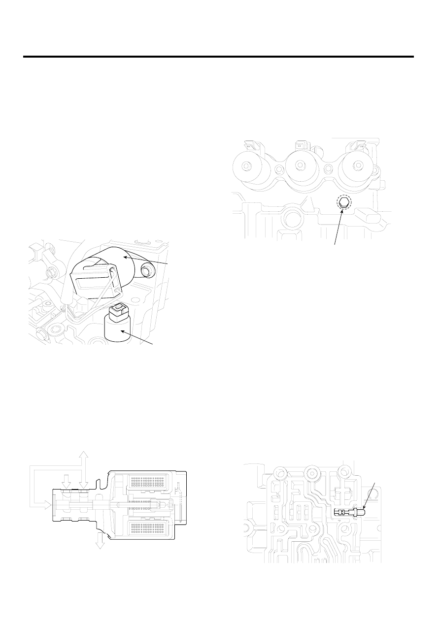
VFS

ATF TEMP SENSOR

EKRF081A

Characteristics of Bosch VFS:
Supply pressure : 700∼1600kPa
Control pressure: typically 600∼0 kPa
Current range: typically 0∼1,000 mA
Dither frequency: Up to 600 Hz
Dimension: 32 mm protrusion reach 42 mm

Control

Supply

Exhaust

EKRF082A

The reducing pressure will be supplied to the ‘ Supply’
port of the VFS valve on the above illustration to control
the line pressure.

REDUCING PRESSURE

FUNCTION

Adjusting screw for reducing pressure

EKRF083A

As same as one of Alpha or Beta automatic transaxle sys-
tem, this reducing valve length can be adjusted by rotating
the screw on the picture. As you rotate the screw toward
clockwise by 90˚ , the reducing pressure will increase
about 1.0bar. However, the reducing pressure is used
just as a ‘ supply pressure’

for the solenoid valves (ex-

cept Low&Reverse, Reduction and Damper Clutch control
solen), so this may not be handled to rotate in the field ser-
vice shop. VFS is operated based on the ‘ supply pres-
sure’

and it outputs the ‘ control pressure’

to control

the regulator valve indirectly. While developing the VFS
system, the line pressure was used as a ‘ supply pres-
sure’

for VFS and other solenoid valves but it has been

changed into additional ‘ reducing pressure’

because

the line pressure is variably changed by VFS so the control
pressure becomes unstable and some hydraulic pressure
oscillation occurred. That is why the reducing pressure
has been added in the hydraulic circuit of VFS system for
both 4th and 5th speed A/T.

<Valve body>

Reducing
valve

EKRF084A

AUTOMATIC TRANSAXLE SYSTEM

AT -17

O/D SOL.

EX

EX

2ND SOL.

EX

U/D SOL.

REDUCING
VALVE

LR SOL.  
RED SOL.

EX

EX

OIL

PUMP

P

control

P

supply

VFS

OIL STRAINER

LINE RELIEF

REGULATOR  V.

EX

EKRF085A

The reducing pressure is about 6.5bar and this value does
not be changed regardless of the driving or engine load
condition. Be sure that the conventional line pressure is
used for the ‘ supply pressure’

of Low&Reverse, Re-

duction solenoid because the variable line pressure is not
available at reverse range.

AT -18

AUTOMATIC TRANSAXLE (F4A51)

HYDRULIC PRESSURE TABLE

Under the constant current amount of VFS (200mA), the
line pressure will become as below table. Be sure that the
following data can be achieved by specific special facility or

device to check the performance of A/T assembly (not on
the vehicle), however we can refer the maximum pressure
value according to each element.

Solenoid valve Duty( % )

LR

2ND

UD

OD

RED*

Mea-

sured El-

ement

Pressure kPa(Psi)

0

100

0

100

0

1030±20(149±3)

60

520±40(75±6)

75

230±40(33±6)

100

LR

0

100

0

0

100

0

1030±20(149±3)

60

550±40(80±6)

75

220±40(32±6)

100

2ND

0

100

100

0

0

0

1030±20(149±3)

60

520±40(75±6)

75

210±40(30±6)

100

OD

0

100

100

0

0

0

1030±20(149±3)

60

470±40(68±6)

75

170±40(25±6)

100

UD

0

100

0

100

0

100

0

75

270±40(39±6)

60

540±40(78±6)

0

DIR*

1030±20(149±3)

Measuring condition:
1.

PG-A (Input speed): 2,500rpm

2.

Manual valve position: D

3.

DCC Solenoid duty: 0%

AUTOMATIC TRANSAXLE SYSTEM

AT -19

N-P

REVERSE CLUTCH

LOW&REVERSE BRAKE

2ND BRAKE

UNDER DRIVE CLUTCH

OVER DRIVE CLUTCH

T

ORQUE

CONVER

TER

DAMPER

CLUTCH

DAMPER CLUTCH

CONTROL

 V

.

T

OROUE CONVER

TER

OIL

 FIL

TER

OIL

 P

A

N

OIL

PUMP

COOLER

PRESS

CHECK POR

T

PRESS

CHECK POR

T

PRESS

CHECK POR

T

PRESS

CHECK POR

T

PRESS

CHECK POR

T

CB6 & CB7

CB4

CB3

ACCUMULA

T

O

R

ACCUMULA

T

O

R

ACCUMULA

T

O

R

ACCUMULA

T

O

R

PRESS

CHECK POR

T

DCC SOL.  V

N/O

LR SOL.  V

N/O

2ND SOL.  V

N/O

UD SOL.  V

N/O

OD SOL.  V

N/O

MANUAL.  V

REDUCING

VA

LV

E

REDUCING PRESSURE CHECK

(ONL

Y

 V/BODY

 ASSY)

R  N  D

     P

LR P

.C.V

2ND P

.C.V

UD P

.C.V

OD P

.C.V

LUBRICA

TION

PRESS

CHECK POR

T

VFS

OIL

 STRAINER

LINE RELIEF

REGULA

T

OR  V

.

EX

EX

EX

EX

EX

EX

EX

EX

EX

EX

EX

EX

EX

EX

EX

EX

EX

EX

EX

EX

EX

EX

EX

SWITCH  V

.

F

AIL

 SAFE V

. - 

A

F

AIL

 SAFE V

. - B

DAMPING

VA

LV

E

CBS

Pressure release

Main pressure

Pump intak

e pressure

Damper clutch apply pressure

T

orque con

v

e

rter and Lubr

ication

Depressed pressure

EKRF017H


Content   ..  14  15  16  17   ..