Hyundai: Engine D4FA. Manual - part 109
DIESEL CONTROL SYSTEM
FLA -307
DTC P0562 SYSTEM VOLTAGE LOW
COMPONENT LOCATION
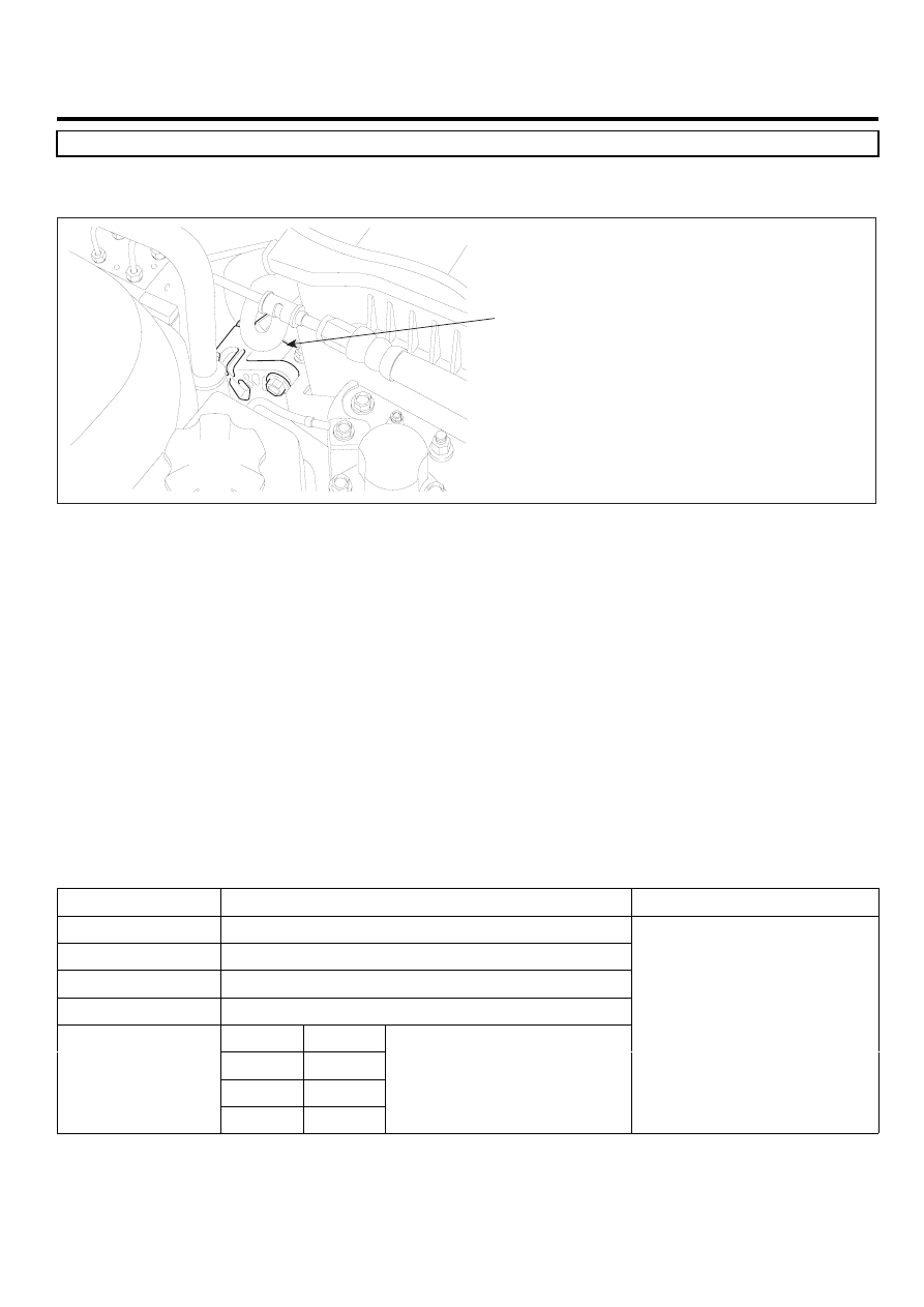
ED191A4D
Alternator
EGNG003M
GENERAL DESCRIPTION
E97DDA44
Normally, battery voltage fluctuates from 11.5V to 14.5V. Especially at cranking, voltage can drop to 9.8V. Therefore,
actuators which require 12V power supply meet fluctuation of power by 5V.A little change of voltage supply can shift
controlling characteristic of actuators, such as injectors, Rail pressure regulator valve and EGR actuator, which should be
controlled delicately. To correct controlling characteristic change arrised from voltage fluctuation, ECM performs actuator
operating correction according to voltage change as detecting battery voltage change.
DTC DESCRIPTION
E513ABDB
P0562 is set when battery voltage below 6V is detected for more than 5 sec. Check charging system.(charging circuit,
alternator component)
▶ ECM senses battery voltage as monitoring the voltages in ECM(C101-2) connector terminal 1,3,5 which are transmitted
from main relay.
DTC DETECTING CONDITION
E1936633
Item
Detecting Condition
Possible Cause
DTC Strategy
• Voltage monitoring
Enable Conditions
• IG KEY "ON"
ThresholdValue
• when battery voltage is below 6V
DiagnosticTime
• 5 sec.
Fuel Cut
NO
EGR Off
NO
Fuel Limit
NO
Fail Safe
MIL
NO
• Charging circuit
• Alternator component