Hyundai: Engine D4FA. Manual - part 84


  Index      Hyundai     Hyundai: Engine D4FA - service repair manual


Search            


Content   ..  82  83  84  85   ..


Hyundai: Engine D4FA. Manual - part 84


DIESEL CONTROL SYSTEM

FLA -207

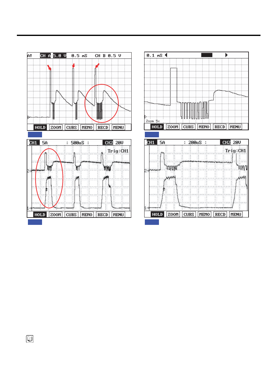
SIGNAL WAVEFORM AND DATA

E2C0B675

Pilot injection1

Pilot injection2

Main injection

Injector current waveform

Fig.1

Fig.2

Fig.3

Fig.4

Fig.1) Injector operating waveform at Low side, It shows 2 pilot and 1 main injection. 
Fig.2) Magnified waveform of main injection at Fig.1)
Fig.3) Injector voltage and current waveforms are measured at the same time using current prove of scope meter.
Fig.4) Magnified waveform of pilot injection at Fig.3)

EGNG008F

TERMINAL AND CONNECTOR INSPECTION

E8C159AA

1.

Electrical systems consist of a lot of harness and connectors, poor connection of terminals can cause various prob-
lems and damge of component.

2.

Perform checking procedure as follows.

1)

Check damage of harness and terminals : Check terminals for contact resistance, corrosion and deformation.

2)

Check connecting condition of ECM and component connector : Check terminal seperation, damage of locking
device and connecting condition between terminal and wiring.

NOTE

Disconnect the pin which requires checking at male connector and insert it to the terminal at female connector for
checking connecting condition. ( after checking, reconnect the pin at correct position. )

3.

Is the problem found?

FLA -208

FUEL SYSTEM

YES

▶ Repair the trouble causing part and go to "Verification of Vehicle Repair".

NO

▶ Go to "Power Circuit Inspection".

POWER CIRCUIT INSPECTION

ED0E36E1

1.

Check open in power circuit(High side)

1)

IG KEY "OFF", ENGINE "OFF".

2)

Disconnect injector #1 connector and ECM connector.

3)

[P0201] Check continuity between injector #1 connector terminal 2 and ECM connector terminal 47.
[P0202] Check continuity between injector #2 connector terminal 2 and ECM connector terminal 31.
[P0203] Check continuity between injector #3 connector terminal 2 and ECM connector terminal 46.
[P0204] Check continuity between injector #4 connector terminal 2 and ECM connector terminal 33.

Specification : Continuity (below 1.0Ω )

4)

Is the measured resistance within the specification?

YES

▶ Go to "Control Circuit Inspection".

NO

▶ Repair open in injector #1 power circuit and go to "Verification of Vehicle Repair".

CONTROL CIRCUIT INSPECTION

EF6EDA56

1.

Check open in control circuit(Low side)

1)

IG KEY "OFF", ENGINE "OFF".

2)

Disconnect injector #1 connector and ECM connector.

3)

[P0201] Check continuity between injector #1 connector terminal 1 and ECM connector terminal 16.
[P0202] Check continuity between injector #2 connector terminal 1 and ECM connector terminal 2.
[P0203] Check continuity between injector #3 connector terminal 1 and ECM connector terminal 1.
[P0204] Check continuity between injector #4 connector terminal 1 and ECM connector terminal 17.

Specification : Continuity (below 1.0Ω )

4)

Is the measured resistance within the specification?

YES

▶ Go to "Component Inspection".

DIESEL CONTROL SYSTEM

FLA -209

NO

▶ Repair open in injector #1 control circuit and go to "Verification of Vehicle Repair".

COMPONENT INSPECTION

EED82859

1.

Check injector component resistance

1)

IG KEY "OFF", ENGINE "OFF".

2)

Disconnect injector connector.

3)

Measure the resistance between injector component terminal 1 and 2.

Specification : 0.255Ω ±0.04 (20℃).

1

2

EGNG008I

4)

Is the measured resistance(of injector solenoid) within the specification?

YES

▶ Go to "Verification of Vehicle Repair".

NO

▶ Replace injector and go to "Verification of Vehicle Repair".

NOTE

Replacing injectors, peculiar IQA code of each injector should be inputted to ECM
Perform this process using "Injector data input" function on scantool, Refer to P1670, P1671 for more detailed infor-
mation.

VERIFICATION OF VEHICLE REPAIR

E7885D4C

After a repair, it is essential to verify that the fault is corrected.

1.

After connecting Scantool select "DIAGNOSTIC TROUBLE CODES(DTCs)" mode.

2.

Clear recorded DTC using Scantool.

3.

Drive the vehicle within DTC "Enable conditions" in "General information".

4.

After selecting "DIAGNOSTIC TROUBLE CODES(DTCs)" mode and check if DTC is recorded again.

5.

Are any DTCs recorded ?

FLA -210

FUEL SYSTEM

YES

▶ Go to the DTC guide of recorded NO. in Scantool.

NO

▶ System operates within specification.


Content   ..  82  83  84  85   ..