Hyundai: Engine D4FA. Manual - part 74


  Index      Hyundai     Hyundai: Engine D4FA - service repair manual


Search            


Content   ..  72  73  74  75   ..


Hyundai: Engine D4FA. Manual - part 74


DIESEL CONTROL SYSTEM

FLA -167

YES

▶ Go to "Component Inspection".

NO

▶ Repair short to ground in signal circuit and go to "Verification of Vehicle Repair".

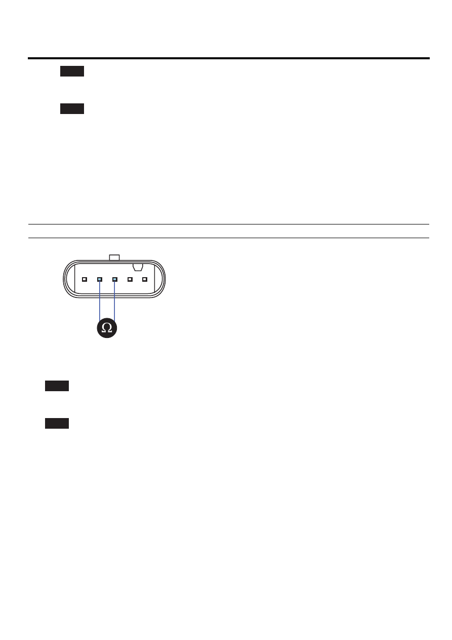
COMPONENT INSPECTION

E428B692

1.

Ignition "OFF", Turn Engine "OFF".

2.

Disconnect MAFS connector.

3.

Measure resistance of IATS component terminal 3 and 2, referring to resistance characteristic table of specification
of General information.

Specification : Refer to Specification of General Information.

EGNG004S

4.

Is the measured resistance at certain temperature within the specified resisance range at the temperature?

YES

▶ Go to "Verification of Vehicle Repair".

NO

▶ Replace MAFS ASSY’ and go to "Verification of Vehicle Repair".

VERIFICATION OF VEHICLE REPAIR

EA50D73E

After a repair, it is essential to verify that the fault is corrected.

1.

After connecting Scantool select "DIAGNOSTIC TROUBLE CODES(DTCs)" mode.

2.

Clear recorded DTC using Scantool.

3.

Drive the vehicle within DTC "Enable conditions" in "General information".

4.

After selecting "DIAGNOSTIC TROUBLE CODES(DTCs)" mode and check if DTC is recorded again.

5.

Are any DTCs recorded ?

FLA -168

FUEL SYSTEM

YES

▶ Go to the DTC guide of recorded NO. in Scantool.

NO

▶ System operates within specification.

DIESEL CONTROL SYSTEM

FLA -169

DTC P0113 INTAKE AIR TEMPERATURE SENSOR 1 CIRCUIT HIGH INPUT

COMPONENT LOCATION

E4A627CA

Refer to DTC P0112.

GENERAL DESCRIPTION

E472BDF9

Refer to DTC P0112.

DTC DESCRIPTION

ED6C8A71

P0113 is set when the voltage above 4886mV - maximum output voltage of IATS - is detected for more than 2.0 sec. This
code is due to 1) open or 2) short to ground or 3) short to battery in IATS signal circuit.

DTC DETECTING CONDITION

E7BE8492

Item

Detecting Condition

Possible Cause

DTC Strategy

• Voltage Monitoring

Enable Conditions

• IG KEY "ON"

ThresholdValue

• When output signal is above the maximum

value ( above 4.886mV )

DiagnosticTime

• 2.0 sec.

Fuel Cut

NO

EGR Off

NO

Fuel Limit

NO

Fail Safe

MIL

NO

• Intake air temperature is

regarded as 50℃

• IATS circuit
• IATS component

SPECIFICATION

EF060A26

Refer to DTC P0112.

SCHEMATIC DIAGRAM

E7F7D236

Refer to DTC P0112.

SIGNAL WAVEFORM AND DATA

E30871A7

Refer to DTC P0112.

MONITOR SCANTOOL DATA

E82AE35E

1.

Connect scantool to Data Link Cable. (DLC)

2.

Warm engine up to normal operating temperature.

3.

Turn "OFF" electrical devices and A/C.

4.

Monitor "AIR TEMPERATURE SENSOR" parameter on the scantool.

FLA -170

FUEL SYSTEM

Specification : Intake air temperature is displayed

Fig.1

Fig.1)  "AIR TEMPERATURE SENSOR" value should not change according to engine state.

EGNG004Q

TERMINAL AND CONNECTOR INSPECTION

E58294E2

Refer to DTC P0112.

SIGNAL CIRCUIT INSPECTION

E7DA0844

1.

Check signal circuit voltage

1)

IG KEY "OFF", ENGINE "OFF".

2)

Disconnect MAFS connector

3)

IG KEY "ON"

4)

Measure the voltage of terminal 3 of MAFS connector.

Specification : 4.8V~5.1V

5)

Is the measured voltage within the specification?

YES

▶ Go to "Component Inspection"

NO

▶ Go to "2.Check open in signal circuit" as follows.

2.

Check open in signal circuit

1)

IG KEY "OFF", ENGINE "OFF".

2)

Disconnect MAFS connector and ECM connector

3)

Check continuity between MAFS connector terminal 3 and ECM connector terminal 89.


Content   ..  72  73  74  75   ..