Hyundai Tiburon (2003 year). Manual - part 71
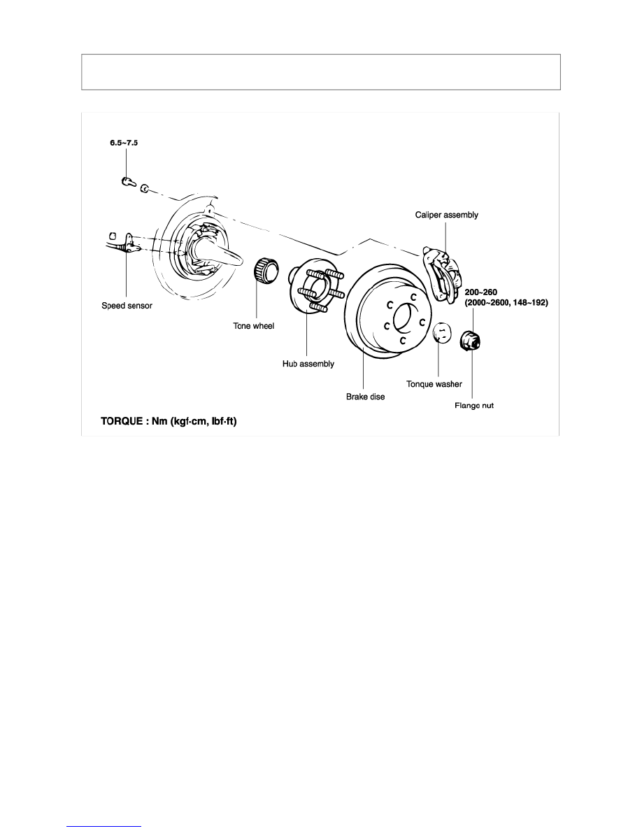
TIBURON(GK) > 2003 > G 2.7 V6 DOHC > Driveshaft and axle > Rear Axle Assembly > Rear Hub / Carrier >
Components and Components Location, TIBURON(GK) > 2003 > G 2.7 V6 DOHC > Driveshaft and axle > Rear
Axle Assembly > Rear Hub / Carrier > Components and Components Location
COMPONENTS