Hummer H2. Manual - part 774
1. Install the longitudinal accelerometer.
2. Install the longitudinal accelerometer retaining screws.
Tighten: Tighten the screws to 2 N.m (18 lb in).
3. Install I/P bezel. Refer to Trim Panel Replacement - Instrument Panel (I/P) Center in Instrument
Panel, Gauges and Console.
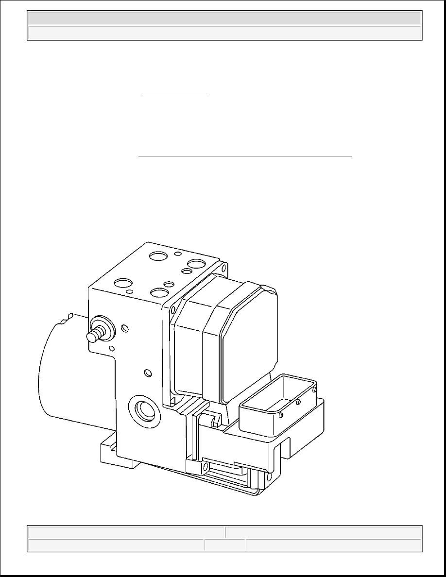
DESCRIPTION AND OPERATION
ABS DESCRIPTION AND OPERATION
NOTE:
Refer to Fastener Notice in Cautions and Notices.
2004 Hummer H2
2004 BRAKES Anti-Lock Brake System - Hummer H2