Hummer H2. Manual - part 359


  Index      Hummer     Hummer H2 - service repair manual 2004 year


Search            


Content   ..  357  358  359  360   ..


Hummer H2. Manual - part 359


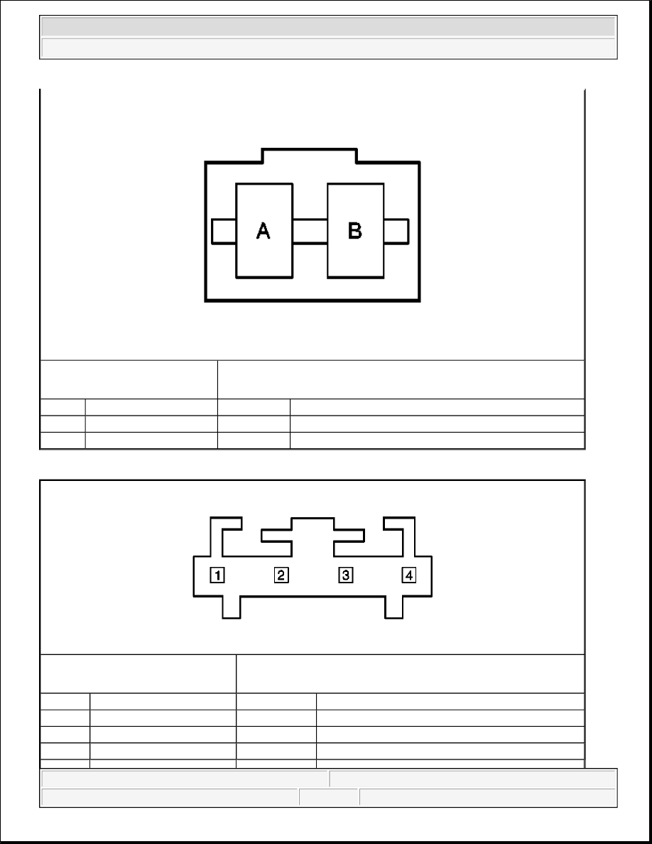
Steering Wheel Controls Terminal Identification - Left Lower (Fuel/Trip) 

Connector Part Information

z

12010105  

z

2-Way F Fuse Holder (BK)  

Pin

Wire Color

Circuit No.

Function

A

BN/WH

230

Steering Wheel Controls Lamps Dimming Control

B

BN/WH

230

Steering Wheel Controls Lamps Dimming Control

Connector Part Information

z

50579404  

z

4-Way F Molex (BLK)  

Pin

Wire Color

Circuit No.

Function

1

BN

230

Steering Wheel Switch Dimming Control

2

YE

1327

DIC Fuel Signal

3

D-BU

894

DIC Toggle Switch Signal


2004 Hummer H2 

2004 ACCESSORIES & EQUIPMENT Instrument Panel, Gauges, and Console - Hummer H2


Steering Wheel Controls Terminal Identification - Right Lower (Personalization/Select) 

Steering Wheel Controls Terminal Identification - Upper Left (Radio-Program/Source) 

4

BLK

1851

Ground

Connector Part Information

z

50579405  

z

5-Way F Molex (BK)  

Pin

Wire Color

Circuit No.

Function

1

BN

230

Steering Wheel Switch Dimming Control

2

D-GN

1358

DIC Switch Signal

3

OG

1816

DIC Set/Reset Switch Signal

4

BLK

1851

Ground

5

-

-

Not Used

Connector Part Information

z

50579405  

z

5-Way F Molex (BK)  

Pin

Wire Color

Circuit No.

Function

1

L-GN

1011

Remote Radio Control Signal


2004 Hummer H2 

2004 ACCESSORIES & EQUIPMENT Instrument Panel, Gauges, and Console - Hummer H2


Steering Wheel Controls Terminal Identification - Upper Right (Radio-Seek/Volume) 

DIAGNOSTIC INFORMATION AND PROCEDURES 

DIAGNOSTIC STARTING POINT - INSTRUMENT PANEL, GAUGES AND CONSOLE 

Begin the system diagnosis with Diagnostic System Check - Instrument Cluster , Diagnostic System Check 
- Driver Information Systems
 or Diagnostic System Check - Audible Warnings . The Diagnostic System 
Check will provide the following information: 

z

The identification of the control module(s) which command the system  

z

The ability of the control module(s) to communicate through the serial data circuit  

z

The identification of any stored diagnostic trouble codes (DTCs) and their status  

2

BN

230

Steering Wheel Switch Dimming Control

3

BK

1851

Ground

4

-

-

Not Used

5

L-GN

1011

Remote Radio Control Signal

Connector Part Information

z

50579406  

z

6-Way F Molex (BLK)  

Pin

Wire Color

Circuit No.

Function

1

WH

2283

12 Volt Reference

2

L-GN

1011

Remote Radio Control Signal

3

BN

230

Steering Wheel Switch Dimming Control

4

-

-

Not Used

5

BK

1851

Ground

6

L-GN

1011

Remote Radio Control Signal


2004 Hummer H2 

2004 ACCESSORIES & EQUIPMENT Instrument Panel, Gauges, and Console - Hummer H2


The use of the Diagnostic System Check will identify the correct procedure for diagnosing the system and 
where the procedure is located. 

Begin the audible warning system diagnosis by reviewing the system operation. Reviewing the operation 
information will help you determine the correct symptom diagnostic procedure when an audible warning 
malfunction exists. Reviewing the operation information will also help you determine if the condition described 
by the customer is normal operation. Refer to Symptoms - Instrument Panel, Gauges and Console in order to 
identify the correct procedure for diagnosing the audible warning system and where the procedure is located. 

DIAGNOSTIC SYSTEM CHECK - INSTRUMENT CLUSTER 

Test Description 

The numbers below refer to the step numbers on the diagnostic table. 

2: Lack of communication may be due to a partial malfunction of the class 2 serial data circuit or due to a 
total malfunction of the class 2 serial data circuit. The specified procedure will determine the particular 
condition.  

4: The symptom list in Symptoms will determine the correct diagnostic procedure to use.  

5: The presence of DTCs which begin with "U" indicate some other module is not communicating. The 
specified procedure will compile all the available information before tests are performed.  

Diagnostic System Check - Instrument Cluster 

Step

Action

Yes

No

Schematic Reference: Instrument Cluster Schematics

1

Install a scan tool. 
Does the scan tool power up?

Go to Step 2

Go to Scan Tool Does Not 

Power Up in Data Link 

Communications

2

1. Turn the ignition ON, with the 

engine OFF.  

2. Attempt to establish 

communication with the 
following control modules: 

z

Transfer Case Electronic 
Control (TREC)  

z

Body Control Module 
(BCM)  

z

Electronic Brake Control 
Module (EBCM)  

z

Instrument Panel Cluster 
(IPC)  

z

Powertrain Control 
Module (PCM)  

z

Sensing and Diagnostic 


2004 Hummer H2 

2004 ACCESSORIES & EQUIPMENT Instrument Panel, Gauges, and Console - Hummer H2


Content   ..  357  358  359  360   ..