Hummer H2. Manual - part 2175


  Index      Hummer     Hummer H2 - service repair manual 2004 year


Search            


Content   ..  2173  2174  2175  2176   ..


Hummer H2. Manual - part 2175


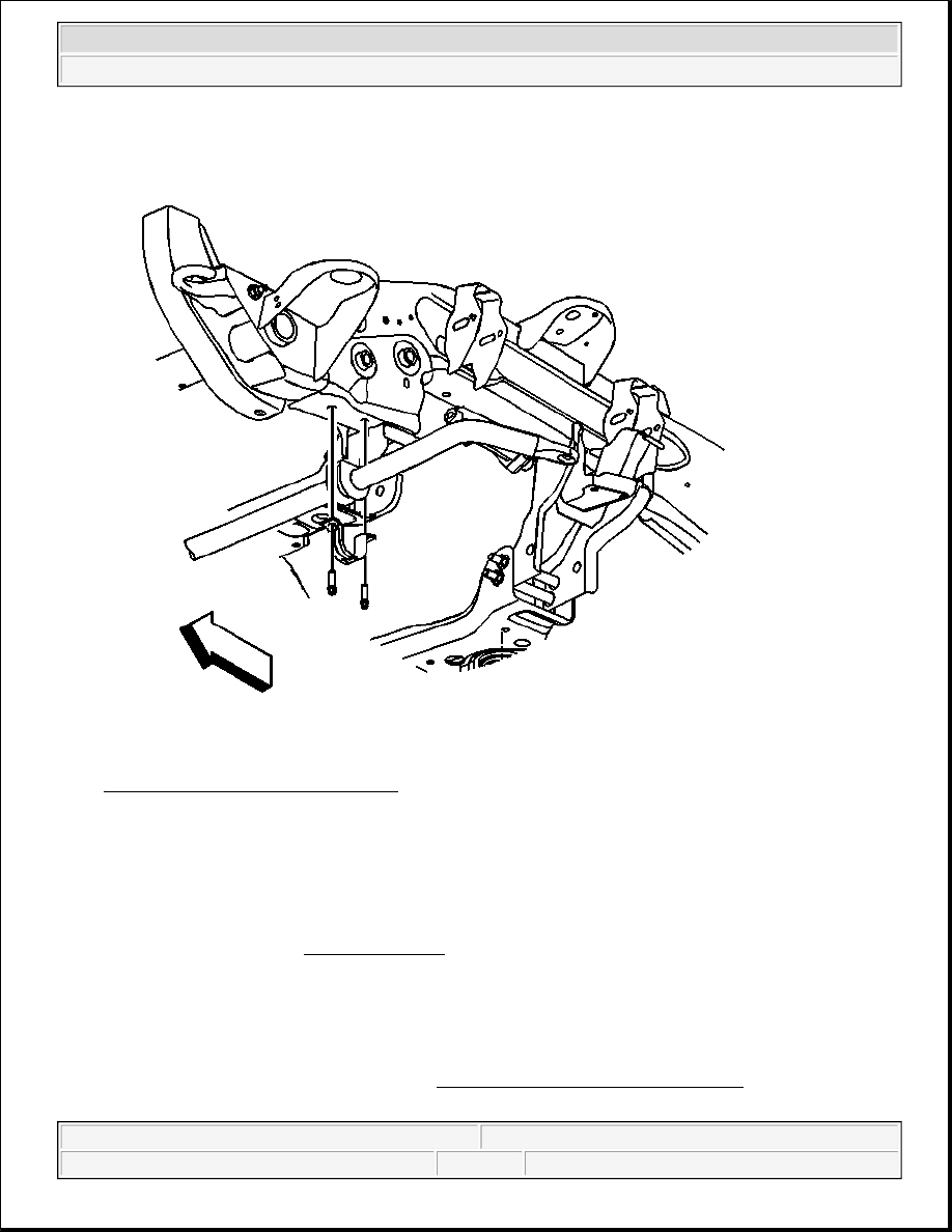
Fig. 10: Insulators & Stabilizer Shaft 
Courtesy of GENERAL MOTORS CORP. 

2. Install the insulators to the stabilizer shaft.  

3. Install the stabilizer shaft.  

4. Install the clamps over the insulators and the stabilizer shaft. 

5. Install insulator clamp bolts. 

Tighten: Tighten the bolts to 50 N.m (37 lb ft). 

6. Install the engine protection shield. Refer to Engine Protection Shield Replacement .  

7. Lower the vehicle.  

NOTE:

Refer to Fastener Notice in Cautions and Notices.


2004 Hummer H2 

2004 SUSPENSION Front Suspension - Hummer H2


LOWER BALL JOINT REPLACEMENT

Removal Procedure 

1. Raise and support the vehicle. Refer to Lifting and Jacking the Vehicle in General Information.  

2. Remove the tire and wheel assembly. Refer to Tire and Wheel Removal and Installation in Tires and 

Wheels.  

3. Remove the lower control arm. Refer to Lower Control Arm Replacement .  

4. Using a press, remove the ball joint from the lower control arm.  

Installation Procedure 

1. Install the new ball joint using a press. 

2. Install the lower control arm. Refer to Lower Control Arm Replacement .  

3. Install the tire and wheel assembly. Refer to Tire and Wheel Removal and Installation in Tires and 

Wheels.  

4. Remove the safety stands.  

5. Lower the vehicle.  

6. Verify the wheel alignment. Refer to Wheel Alignment Specifications in Wheel Alignment.  

STEERING KNUCKLE REPLACEMENT 

Tools Required 

J 43631 Ball Joint Remover. See Special Tools and Equipment . 

J 45851 Ball Joint Separator Protector Adaptor. See Special Tools and Equipment . 

Removal Procedure 

1. Raise and support the vehicle. Refer to Lifting and Jacking the Vehicle in General Information.  

2. Remove the tire and wheel. Refer to Tire and Wheel Removal and Installation in Tires and Wheels.  

3. Support the lower control arm.  

4. Remove the wheel hub and bearing assembly. Refer to Wheel Hub, Bearing, and Seal Replacement .  

5. Disconnect the outer tie rod to the steering knuckle. Refer to Tie Rod Replacement - Outer in Steering 

Linkage (Non- Rack and Pinion).  

6. Remove the brake hose bracket retaining bolt from the steering knuckle.  

7. Remove the upper control arm retaining nut and separate the upper ball joint from the steering knuckle 

using the J 43631 and the J 45851 . See Special Tools and Equipment 

IMPORTANT: Use the outer flange of the ball joint in order to press the ball joint into 

place.


2004 Hummer H2 

2004 SUSPENSION Front Suspension - Hummer H2


Fig. 11: Lower Ball Joint & Steering Knuckle 
Courtesy of GENERAL MOTORS CORP. 

8. Remove the lower control arm retaining nut. Separate the lower ball joint from the steering knuckle (2) 

using the J 43631 and the J 45851 (1). See Special Tools and Equipment 


2004 Hummer H2 

2004 SUSPENSION Front Suspension - Hummer H2


Fig. 12: Identifying Steering Knuckle 
Courtesy of GENERAL MOTORS CORP. 

9. Remove the steering knuckle.  

Installation Procedure 

1. Clean all grease and contaminants from the tapered section and the threads of the upper ball joint, the 

lower ball joint, and the tie rod end.  

2. Clean and inspect the taper holes and the mounting surfaces of the steering knuckle. If any of the tapered 

holes are elongated, out of round, or damaged, replace the steering knuckle. 


2004 Hummer H2 

2004 SUSPENSION Front Suspension - Hummer H2


Content   ..  2173  2174  2175  2176   ..