Hummer H2. Manual - part 2058


  Index      Hummer     Hummer H2 - service repair manual 2004 year


Search            


Content   ..  2056  2057  2058  2059   ..


Hummer H2. Manual - part 2058


SCAN TOOL DATA LIST 

The SIR Scan Tool Data List contains all the restraint system related parameters that are available on the scan 
tool. The parameters in the list are arranged in alphabetical order. The column, "Data List," indicates the 
location of the parameter within the scan tool menu selections. 

Use the SIR Scan Tool Data List as directed by a diagnostic table or in order to supplement the diagnostic 
procedures. Begin all of the diagnostic procedures with the SIR Diagnostic System Check. Use the SIR Scan 
Tool Data List after the following are determined: 

z

There is no published DTC procedure nor published symptom procedure for the customer concern.  

z

The DTC or symptom diagnostic procedure indicated by the diagnostic system check does not resolve the 
customer concern.  

The Typical Data Values are obtained from a properly operating vehicle under the conditions specified in the 
first row of the Scan Tool Data List table. Comparison of the parameter values from the suspect vehicle with the 
Typical Data Values may reveal the source of the customer concern.
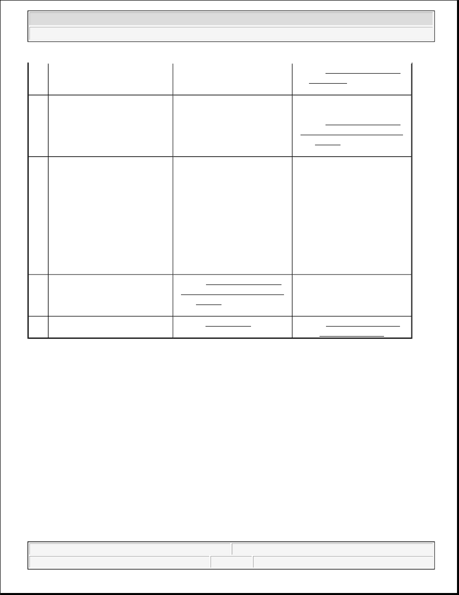
2

Install a scan tool. 
Does the scan tool power up?

Go to Step 3

Go to Scan Tool Does Not 

Power Up in Data Link 

Communications

3

Attempt to establish 
communication with the 
inflatable restraint sensing and 
diagnostic module (SDM). 
Does the scan tool communicate 
with the SDM?

Go to Step 4

Go to Scan Tool Does Not 

Communicate with Class 2 

Device in Data Link 

Communications

4

1. Use the scan tool to 

request the SIR diagnostic 
trouble code (DTC) 
display.  

2. Record the displayed DTC

(s) on the repair order, 
specifying as current or 
history.  

Does the scan tool display any 
current or history DTCs?

Go to Step 5

System OK

5

Does the scan tool display any 
DTC's which begin with a "U"?

Go to Scan Tool Does Not 

Communicate with Class 2 

Device in Data Link 

Communications

Go to Step 6

6

Does the scan tool display DTC 
B1000?

Go to DTC B1000 in Body 

Control System

Go to Diagnostic Trouble 

Code (DTC) List


2004 Hummer H2 

2004 RESTRAINTS SIR - Hummer H2


SIR Scan Tool Data List 

SCAN TOOL DATA DEFINITIONS 

The SIR scan tool data definitions contain a brief description of all SIR related parameters available on the scan 
tool. The parameters that are available on the scan tool are listed below in alphabetical order. 

8 Digit GM Part Number  

The scan tool displays an 8 digit part number. This number is the GM part number that is stored within 
the SDM memory. 

Active Switch  

The scan tool displays enabled or disabled. The signal from the inflatable restraints I/P module disable 
switch indicates whether the passenger frontal air bag is enabled or disabled. 

Calibration ID  

The scan tool displays a 4 digit number. This calibration ID is the check sum of the SDM read only 
memory contents. 

Component Serial Number  

The scan tool displays the digits of the SDM serial number. 

Driver Side Belt Status  

The scan tool displays Buckled or Unbuckled. The signal from the drivers seat belt switch indicates 
whether the driver seat is buckled or unbuckled.

Scan Tool Parameter

Data List

Units Displayed

Typical Data Value

Ignition ON/Engine OFF/Driver Seat Belt Buckled/Active Switch Enabled

8-Digit GM Part Number

Module Information 2

8-digit number

XXXXXXXX

Active Switch

Inputs

Enabled/Disabled

Enabled

Calibration ID

Module Information 1

4-digit number

Varies

Component Serial Number

Module Information 2

4-digit number

XXXX

Driver Side Belt Status

Inputs

Buckled/Unbuckled

Buckled

Electronic Front End Sensor 1 ID

Module Information 1

2-digit number

Varies

Electronic Front End Sensor 2 ID

Module Information 1

2-digit number

Varies

Ignition Voltage

Data

Volts

12 volts

Julian Date of Build

Module Information 1

3-digit number

Varies

ROM ID

Module Information 1

4-digit number

Varies

Year Module Built

Module Information 1

4-digit number

Varies


2004 Hummer H2 

2004 RESTRAINTS SIR - Hummer H2


Electronic Front End Sensor ID  

The scan tool displays a 2 digit ID number. The ID signal is sent to the SDM from the front end sensor. 

Ignition Voltage  

The scan tool displays 0-20 volts. The Ignition represents the system voltage measured by the SDM at its 
ignition feed. 

Julian Date of Build  

The scan tool displays a 3 digit number. Which represents the day of the year the module was built. 

ROM ID  

The scan tool displays a 4 digit number. This number is the programmable read-only memory (PROM) 
ID. 

Year Module Built  

The scan tool displays what year the module was built. 

DIAGNOSTIC TROUBLE CODE (DTC) LIST 

Diagnostic Trouble Code (DTC) List 

DTC B0016, B0017, OR B0018 

Circuit Description 

The passenger deployment loop consists of a inflatable restraint I/P module, the I/P module high and I/P module 

DTC

Description

Module

B0016, B0017, or B0018

DTC B0016, B0017, or B0018

SDM

B0022, B0024, or B0026

DTC B0022, B0024, or B0026

SDM

B0051

DTC B0051

SDM

B0053

DTC B0053

SDM

B0090

DTC B0090

SDM

B0091

DTC B0091

SDM

B0100, B0101, B0102, B0103, 

B0104, or B0105

DTC B0100, B0101, B0102, B0103, 
B0104, or B0105

SDM

B1001

DTC B1001

SDM

U1001 - U1254

DTC U1001-U1254 in Data Link 
Communications

EBCM, Passlock Module, 
PCM, SDM, VIM

U1300 and U1301

DTC U1300, U1301, or U1305 in Data 
Link Communications

EBCM, Passlock Module, 
PCM, SDM, VIM


2004 Hummer H2 

2004 RESTRAINTS SIR - Hummer H2


low circuits. There is a shorting bar used within the I/P module connector which will short together both I/P 
module high and low circuits when the connector is disconnected, this will help to prevent unwanted 
deployment of the inflator module during servicing. During a frontal crash of sufficient force the inflatable 
restraint sensing and diagnostic module (SDM) will allow current to flow through the deployment loop in order 
to deploy the I/P module. The SDM performs continuous diagnostic tests on the deployment loops to check for 
proper circuit continuity and for shorts to ground or voltage. If a malfunction is detected, a diagnostic trouble 
code (DTC) will be stored in memory. 

Conditions for Running the DTC 

Ignition 1 voltage is within the normal operating voltage range. 

Conditions for Setting the DTC 

z

DTC B0016 will set when the I/P module deployment loop resistance is less than 1.3 ohms for 500 
milliseconds.  

z

DTC B0017 will set when one of the following conditions occurs: 

{

I/P module high circuit is less than 2.4 volts and the I/P module deployment loop is more than 6 
ohms for 500 milliseconds.  

{

I/P module deployment loop resistance is more than 4.8 ohms for 500 milliseconds.  

z

DTC B0018 will set when one of the following conditions occur: 

{

I/P module high and/or low circuits is short to ground or short to voltage for 500 milliseconds.  

{

I/P module high circuit is less than 2.4 volts and I/P module deployment loop resistance is less than 
6 ohms for 500 milliseconds.  

Action Taken When the DTC Sets 

The SDM commands the AIR BAG indicator ON via Class 2 serial data. 

Conditions for Clearing the DTC 

z

The condition responsible for setting the DTC no longer exists and the scan tool Clear DTCs function is 
used.  

z

A history DTC will clear once 255 malfunction free ignition cycles have occurred.  

Diagnostic Aids 

The following are possible causes of the malfunction: 

z

A short between the I/P module high and low circuits.  

z

An open or a high resistance in the I/P module high or low circuits.  

z

A short to ground or a short to voltage in the I/P module high or low circuits.  

z

The I/P module connector  

z

The SDM connector  


2004 Hummer H2 

2004 RESTRAINTS SIR - Hummer H2


Content   ..  2056  2057  2058  2059   ..